The Core Role of PCB Board Soldering Machines in Electronics Manufacturing
In the electronics manufacturing process, PCB board soldering machines are one of the key links determining product reliability and consistency. Whether it’s through-hole soldering, reflow soldering, or selective soldering, the capability and stability of the soldering equipment directly affect solder joint quality, production efficiency, and the long-term performance of the final product.
From a manufacturing perspective, soldering is not simply “melting solder,” but a systematic engineering process highly dependent on temperature control, time management, and process matching. The core value of PCB board soldering machines lies in achieving stable connections of a large number of solder joints in a controllable and repeatable manner. Compared to manual soldering, automated soldering equipment can significantly reduce the uncertainty caused by human variation, which is an indispensable foundation for the large-scale production of modern electronic products.
As the complexity of PCB design continues to increase, the importance of soldering equipment is further amplified. Multilayer boards, high-copper-thickness PCBs, fine-pitch packages (such as QFN, BGA, LGA), and mixed assembly processes place higher demands on the soldering process. Soldering equipment not only needs to provide sufficient heat energy but also must ensure uniform heat distribution to avoid localized overheating or underheating, thereby reducing typical soldering defects such as cold solder joints, poor solder joints, and bridging.
From a quality control perspective, a PCB board soldering machine acts as an “amplifier” of soldering consistency. If equipment parameters are set improperly, problems will be quickly and extensively replicated; conversely, when the equipment is stable and the process window is clear, it can consistently output highly consistent soldering results in large-scale production. Therefore, soldering equipment is both a source of risk and a guarantee of reliability; the key lies in its correct understanding and use.
At the market level, the ability to select and apply soldering equipment has become an important indicator of an electronics manufacturing company’s engineering strength. Factories with multiple types of soldering equipment and the ability to flexibly switch process solutions according to product characteristics are often better equipped to handle complex projects and small-batch, multi-variety orders. This is particularly evident in the prototyping stage, rapid iteration projects, and the manufacturing of high-reliability products.
In conclusion, a PCB board soldering machine is not merely a piece of equipment on the production line, but a crucial bridge connecting design, process, and quality. The depth of understanding of a PCB’s capabilities and process adaptability often determines whether a PCB can be soldered, or whether it is soldered reliably and stably.
Common PCB Board Soldering Machine Types and Applicable Scenarios
In actual production, the selection of soldering equipment often directly determines the upper limit of soldering quality. Different types of PCB board soldering machines are not simple substitutes, but rather exist to meet specific process requirements and product structures. Understanding the applicable boundaries of these machines is a prerequisite for avoiding soldering defects and manufacturing efficiency issues.
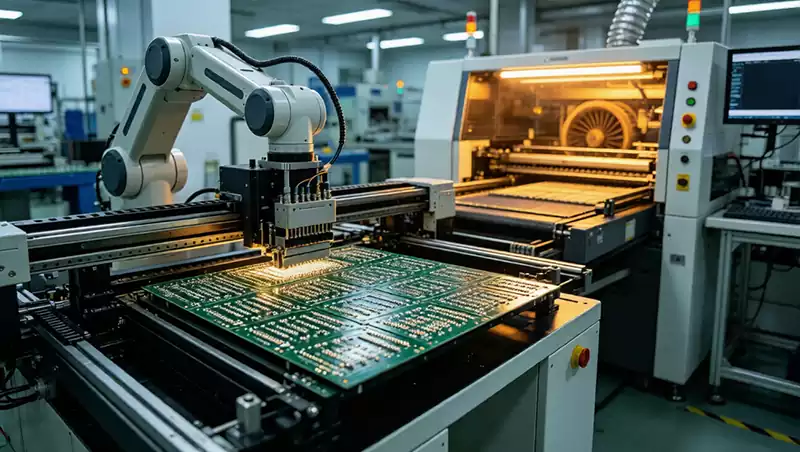
Reflow Soldering Machines are currently the most widely used soldering equipment in SMT processes, primarily used for soldering surface mount devices. Through multi-temperature zone control, reflow soldering can precisely manage the heating, holding, and reflow stages, allowing the solder paste to wet and solidify under controlled conditions. It is particularly suitable for high-density, miniaturized designs and is an indispensable device for fine-pitch packages such as BGA and QFN. However, when the PCB copper thickness is large or the thermal capacity of components varies significantly, the requirements for profile settings and thermal equalization in reflow soldering become significantly higher.
Wave Soldering Machines are primarily used for soldering through-hole components and still hold an irreplaceable position in traditional through-hole designs. Their advantages lie in high soldering efficiency and strong solder joint filling capability, making them suitable for high-volume products with relatively fixed structures. However, wave soldering imposes more restrictions on PCB design; for example, pad layout, component spacing, and solder shielding design all need to be planned in advance, otherwise problems such as solder bridging and missing solder joints can easily occur.
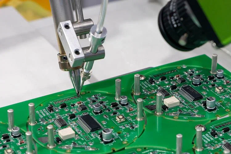
Selective Soldering Machines fall between reflow soldering and wave soldering, specifically designed for mixed-assembly boards or partial through-hole soldering. By precisely controlling the soldering area, it can complete soldering without affecting surrounding components, significantly improving process flexibility. Selective soldering is particularly suitable for small to medium batches of diverse products, but its equipment investment and programming complexity are relatively higher.
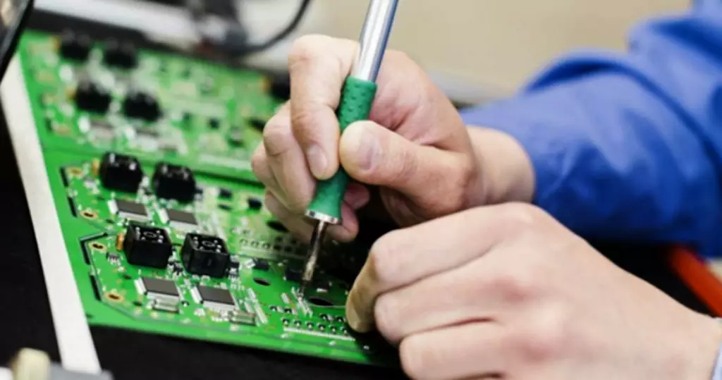
Manual or semi-automatic soldering equipment, while having a lower level of automation, still plays an important role in prototyping, rework, and small-batch trial production. They provide flexibility for engineering verification, but are highly dependent on operator experience and have inherent limitations on soldering consistency and long-term reliability, therefore they are not suitable as the main solution for mass production.
From an engineering practice perspective, truly mature production lines often don’t rely on a single PCB board soldering machine, but rather on a combination of multiple devices to cover different process requirements. The key is not the number of machines, but understanding the capabilities of each machine and matching appropriate soldering solutions in advance during the design and manufacturing stages.
Typical Quality Risks and Misconceptions Related to PCB Board Soldering Machines
In actual production, soldering quality problems are often initially attributed to the PCB board soldering machine itself. However, from an engineering perspective, problems directly caused by equipment hardware defects are relatively few. More often, the problems stem from misunderstandings of equipment capabilities, process windows, and product characteristics.
One of the most common misconceptions is over-reliance on default equipment parameters. Modern soldering equipment typically has a large number of built-in mature process templates, which can indeed quickly start production on standard products. However, once the PCB structure changes, such as increased copper thickness, multi-layer stacking, or concentrated distribution of high-heat-capacity components, these default parameters often become inapplicable. If standard curves are still used, it can easily lead to insufficient or overheating of local solder joints, resulting in cold solder joints, poor soldering, or component damage.
The second type of risk comes from the underestimation of uneven heat distribution. Even with high-performance soldering equipment, significant differences in temperature rise rates and peak temperatures can still exist across different areas. Large areas of grounded copper foil, metal shielding, or power devices absorb substantial heat, creating so-called “cold zones.” If process adjustments are based solely on average temperatures, ignoring local variations, soldering defects often concentrate in specific areas and exhibit high repetition.
The third common misconception is attributing design problems to insufficient equipment capabilities. For example, issues like inappropriate pad sizes, via solder bleed, and insufficient component spacing are essentially rooted in the PCB design phase but often only become apparent during soldering. Simply increasing temperatures or extending reflow times might temporarily improve solder joint appearance but sacrifices component reliability and may even introduce new defects.
Furthermore, equipment maintenance is easily overlooked. The performance of PCB board soldering machines is not static; aging of the conveyor system, heating modules, and temperature sensors gradually narrows the usable process window. Without regular calibration and maintenance, even if process parameters appear unchanged, actual soldering results can deviate significantly.
Finally, an easily overlooked risk is insufficient process validation. When introducing new products or switching processes, directly scaling up production based solely on a small number of sample confirmations often leads to a concentrated outbreak of soldering problems at increased scale. The apparent stability of soldering equipment in small batches does not guarantee consistent performance under prolonged, high-load operation.
In summary, a PCB board soldering machine acts like a magnifying glass. When the design and process are properly matched, it can reliably replicate high-quality solder joints; however, when the understanding is inadequate, it can efficiently replicate problems. The key to truly reducing soldering risks lies not in replacing equipment, but in accurately matching equipment capabilities with product characteristics.
How to Improve Mass Production Stability Through PCB Board Soldering Machines
In the mass production stage, the core value of a PCB board soldering machine lies not in the “ultimate performance” of its soldering capabilities, but in long-term, predictable, and consistent output. To achieve this goal, soldering equipment must be integrated into systematic process management, rather than operating in isolation.
First, a targeted soldering process strategy should be established based on the product structure. Different PCBs vary significantly in copper thickness, number of layers, component distribution, and heat capacity, making a uniform soldering solution impossible. By combining prototype verification results with targeted parameter settings for welding equipment before mass production, the fluctuation range of welding results can be effectively reduced, laying the foundation for stable production.
Secondly, welding equipment should participate in the DFM (Design for Manufacturability) feedback loop. By observing recurring problem areas during welding, design defects can be located in reverse, and optimizations can be made in subsequent versions. Compared to simply adjusting equipment parameters, this “design-manufacturing collaboration” approach often fundamentally improves welding quality.
Thirdly, stable mass production relies on continuous monitoring and regular verification. Reflow soldering profile drift, temperature control module aging, or conveyor system malfunctions can all erode welding consistency imperceptibly. Through regular profile testing, weld spot inspection, and equipment condition assessment, timely intervention can be made before problems escalate, avoiding large-scale quality risks.
Furthermore, in an environment where multiple products are produced in parallel, a reasonable strategy for using welding equipment should be planned. Producing products with similar process requirements together and reducing frequent parameter switching helps improve overall stability and production efficiency. This optimization at the production organization level is often more practically significant than simply improving equipment performance.
Finally, the value of soldering equipment is inseparable from personnel’s understanding of its capabilities. Continuous training of operators and engineers to accurately identify the causes of abnormal solder joints and make correct judgments regarding equipment, processes, and design is crucial for achieving long-term stable production.
Overall, a PCB board soldering machine is not a “cure-all” for soldering problems, but rather an engineering tool that needs to be used correctly and continuously managed. Soldering quality truly becomes scalable only when equipment, processes, and design work in synergy.
Summary
PCB Board Soldering Machine: A True Reflection of Manufacturing Capability
Reviewing the entire soldering process reveals that the PCB board soldering machine is not an isolated production device, but a critical node connecting design, processes, and quality control. It neither automatically “fixes” design defects nor replaces engineering judgment, but it amplifies the results of early-stage decisions in production.
In the prototyping stage, soldering equipment helps the engineering team verify the manufacturability of the design; in mass production, it determines solder joint consistency, yield stability, and the controllability of delivery risks. A truly mature manufacturing system doesn’t rely on the most expensive equipment, but rather on a clear understanding of the equipment’s capabilities and its effective integration with product characteristics, process strategies, and personnel experience.
From a market perspective, the configuration and usage level of PCB board soldering machines have become a crucial indicator of an electronics manufacturing company’s engineering capabilities. Factories capable of consistently delivering reliable soldering quality across different product types and batch sizes are typically more valuable for long-term partnerships.
Therefore, the significance of soldering equipment goes beyond simply “soldering boards well,” but lies in providing a solid foundation for product reliability and manufacturing replicability. The success of mass production is often determined the moment the soldering equipment is understood and managed.