When a circuit design has been tested many times and confirmed to be feasible, it is necessary to consider how to make the breadboard permanent to ensure the stability and durability of the circuit. Breadboards are an extremely common tool in electronic design and prototyping.It allows engineers and hobbyists to quickly build circuits without the need for soldering.However, due to the loose connection of the breadboard, it is easy to have problems such as poor contact and loose cables in practical applications.
Why make breadboards permanent
How to make a breadboard permanent? Breadboards are useful in the early stages of circuit design, but they are not suitable for long-term use.
Here are a few main reasons:
Unstable connection: The metal jacks of the breadboard are maintained by elastic contact, which can lead to metal fatigue and increased contact resistance over time, which in turn leads to circuit instability. Poor durability: Breadboards’ plastic materials, while easy to use, are not able to withstand long-term temperature changes, mechanical vibrations, and humid environments, and are prone to damage.
Layout confusion: As circuits become more complex, jumpers and components on breadboards can become difficult to manage, making debugging and maintenance difficult.
Signal interference: Due to the non-standard wiring method of the breadboard, it is easy to cause signal interference, especially in high-frequency circuits, which can seriously affect the performance of the circuit.
Therefore, when a circuit design is confirmed to be feasible and needs to be operated for a long time, it is important to consider how to make the breadboard permanent to ensure its reliability and maintainability.
The basic method of how to make the breadboard permanent
At present, there are several common methods to perpetuate breadboards, each of which has its own application scenarios and advantages and disadvantages.
1. Use Perfboard (Universal PCB) Perfboard is a type of circuit board with pre-drilled holes, which has the advantages of low production cost, easy hand soldering, and suitable for small DIY projects.
The specific steps are as follows:
Draw the circuit layout: Refer to the wiring method on the breadboard and arrange the direction of components and wires on the perforated board.
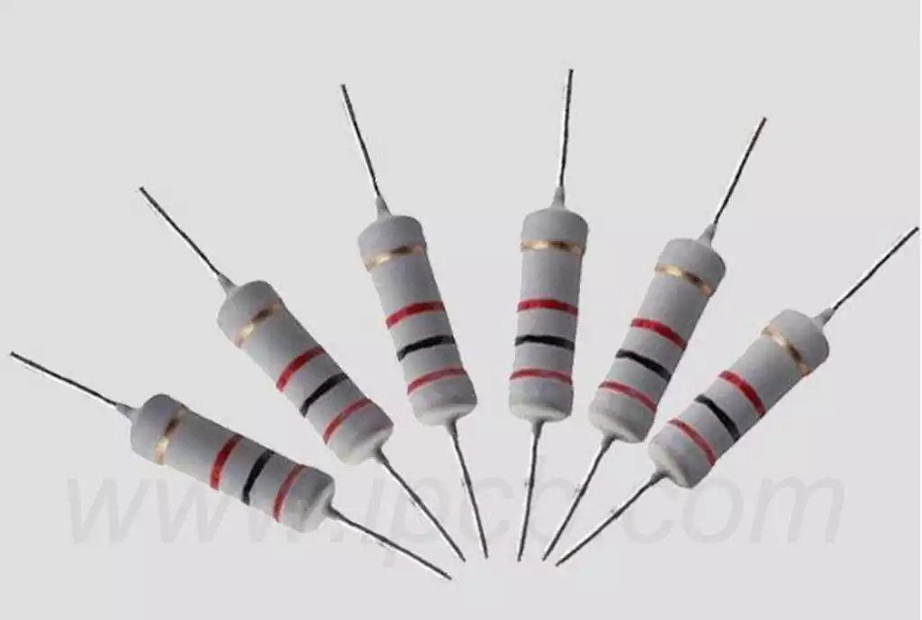
Fixing the component: The pins of the electronic component are inserted into the holes in the perforated plate and fixed with solder.
Connect the wires: Connect the individual electronic components with wires and solder to ensure that the circuit is connected.
Test the circuit: After the soldering is completed, use a multimeter to check the connectivity, and perform a functional test.
Perforated boards are suitable for small circuits, but their layout is not as good as custom PCB specifications, so it may not be optimal for complex circuits. Perforated boards, while inexpensive and readily available, are often not suitable for handling complex signals or high-frequency circuits, as the complexity of wiring and irregular conductivity can lead to reflections and interference of signals.
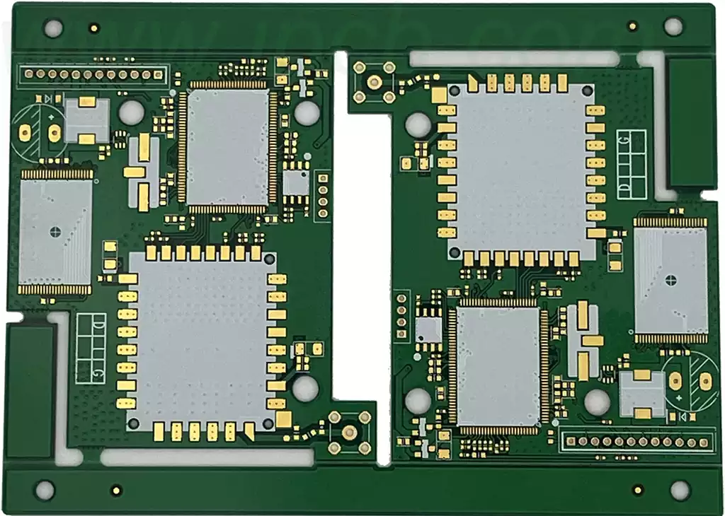
2. Design and Manufacture Custom PCB Custom PCB (Printed Circuit Board) is a more professional choice, which not only improves the reliability of the circuit, but also optimizes the electrical performance.
The process for making breadboards permanent is as follows:
Use PCB design software, such as KiCad, Eagle, or Altium Designer, to draw circuit schematics and design PCB layouts. The design needs to consider the functional requirements of the circuit, the layout of the components, and the rationality of the wiring.
Optimized routing: Ensure proper routing, reduce electromagnetic interference, and improve signal integrity. For example, try to avoid the intersection of long wires and power lines and use a Ground Plane to reduce noise.
Fabricating PCBs: You can choose DIY etching, or submit the design files to a professional PCB manufacturer for production. Professional manufacturers often offer more customization options, such as multi-layer boards, blind or buried via designs, and more.
Soldering components: Electronic components are fixed to the PCB using hand soldering or reflow soldering techniques.
For small circuit boards, manual soldering is usually sufficient, but for mass production or complex circuits, reflow or wave soldering is more efficient.
Functional test: After completing the soldering, the circuit test is carried out to ensure that it works properly.
During the test, use tools such as oscilloscopes, multimeters, and other tools to check the current, voltage, and waveform to ensure that the circuit meets the design requirements.
Custom PCBs are suitable for complex circuits and mass production, and despite the high upfront cost, they are the most stable and reliable solution in the long run. By designing a reasonable PCB, the anti-interference ability of the circuit can be improved, the signal transmission can be optimized, and the long-term stable operation of the circuit can be ensured. For mass production, custom PCBs are the only option worth considering, as it allows for efficient, large-scale production with greater reliability and consistency.
3. Adopt modular circuit
For some applications, off-the-shelf electronic modules, such as microcontroller modules such as Arduino, Raspberry Pi, ESP8266, etc., can be utilized, combined with sensor modules, relay modules, etc., to reduce the amount of soldering and debugging. This approach is suitable for rapid development and small projects, but flexibility can be limited.
Modular circuits typically do not require complex circuit board design, and can be spliced and configured with existing modules, greatly reducing development time. For example, the Arduino platform provides rich hardware interfaces and rich library support, so users only need to connect existing modules (such as temperature sensors, photoresistors, etc.) to the Arduino board and program them for control. While modular circuitry is simple, it may not meet all requirements in large-scale projects, so it is more suitable for the prototyping phase, where the circuit still needs to be designed as a custom PCB.
How to improve the stability of the circuit
In practice, how to make a breadboard permanent is not only about fixing the components, but also about the stability and durability of the circuit.
Here are some key tips:
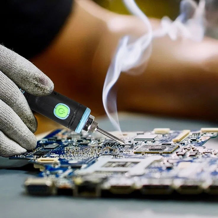
1. Choosing the Right Welding Tools and Materials Soldering is a core step in making a breadboard permanent and requires the right tools, such as:
Solder wire: Lead-free solder with flux is recommended to reduce oxidation issues. Lead-free solder has a higher melting point, so higher temperature control is required when soldering.
Soldering station: Temperature-controlled soldering station can effectively avoid overheating and damage to components. It is recommended to use a welding table with constant temperature control to ensure a stable welding temperature.
Flux: Improve the quality of solder joints and avoid cold soldering. The right flux can improve soldering efficiency and prevent defective solder joints.
The quality of the solder directly affects the stability of the circuit, and it is crucial to ensure the firmness and conductivity of each solder joint. If the solder joints are bad, it may cause the circuit to be unstable or even not work properly.
2. Adopt appropriate insulation and protection After soldering, critical components can be encapsulated with heat shrink tubing, insulating tape, or potting compound for durability and safety. For high-frequency circuits, metal housings or shielding boxes can be used to reduce electromagnetic interference.
3. Conduct reliability tests In order to ensure the long-term stable operation of the circuit, the following tests can be performed:
Vibration test: Simulates the vibration environment that may be encountered during transportation and use. By testing the operation of the circuit at different vibration frequencies and amplitudes, the seismic performance of the circuit can be judged.
High and low temperature test: test the working condition of the circuit in different temperature environments. Extreme temperature conditions can affect the performance of components, so it is important to ensure that the circuit can operate reliably over a wide range of temperatures.
Long-run testing: Let the circuit work continuously for a period of time to identify potential problems. Especially in high-power applications, long-running tests can reveal possible problems such as overheating, power instability, etc.
4. Protection against electromagnetic interference (EMI)
Electromagnetic interference (EMI) is a common stability issue for high-frequency circuits. When designing a PCB, the following measures should be employed to reduce EMI:
Use the Ground Plane to reduce signal interference and ground noise. Make sure that the length of the signal line is as short as possible to avoid signal reflection caused by long wires.
Appropriate filters, isolators, and other components are used to suppress unwanted high-frequency noise.
Case analysis
Case 1: LED Light Control Circuit An electronics enthusiast made an LED light control circuit, and after successfully testing it on a breadboard, he decided to use a perforated board for soldering and adding a housing to make it a long-term night light.
Case 2: Smart Home Automation System An engineer designed a Wi-Fi-based home automation controller, initially prototyped it on a breadboard, and after many tests, he used Altium Designer to design the PCB, commissioned the manufacturer, and finally launched a stable smart home control device.
Case 3: Wireless Temperature Control System A start-up company developed a wireless temperature control system for smart homes, initially using breadboards to build prototypes, and successfully tested communication and temperature control functions. Subsequently, they decided to make the circuit permanent, opted for a custom PCB to reduce size and improve reliability, and finally launched it to the market with positive feedback.
Summary
How to make a breadboard permanent is a step that cannot be ignored in electronic design. Whether you’re using perforated boards, custom PCBs, or a modular approach, each approach has its own scenarios. For simple circuits, using perforated boards is an affordable option, while for circuits that are complex or long-lasting, designing and manufacturing custom PCBs is the best option.
With proper layout, reliable soldering, and adequate testing, the long-term stability of the circuit can be ensured, making it a truly reliable electronic device. Ensuring that a circuit can operate reliably for a long time, especially in a commercial or industrial environment, requires attention to every detail and the right permanent method according to the environment and needs of the circuit.