In the design of modern electronic products, audio input and output are very important, especially in the design of audio equipment. As part of the audio equipment, the mono input jack is often used to receive audio signals from external devices.
In order for figuring out how to wire pcb mono input jack properly, we usually need to connect it to the circuit board (PCB). In this article, we will take a deep look at how to connect a PCB mono input jack and what to pay attention to during the design process.

Understanding Mono Input Jacks
Before you start designing, you must first understand how mono input jacks work. Mono jacks are usually used to receive audio signals from external devices, which may include microphones, guitars, electronic instruments, etc. The typical form of a mono jack is a 3.5mm or 6.35mm jack, which usually has three pins: one for signal input, one for ground, and another for power (if necessary).
The difference between mono and stereo
We need to clarify the difference between mono and stereo jacks. A mono jack has only one signal path and one ground path, while a stereo jack has two signal paths, one for the left channel and one for the right channel. When designing a circuit, if you want to process stereo signals, you need to choose a stereo jack and make appropriate modifications to the circuit.
Choose the right mono input jack
Choosing the right jack is crucial to the stability and sound quality of the circuit. Common mono input jacks come in a variety of models, such as 3.5mm jacks and 6.35mm jacks. The former is usually used for small devices, while the latter is suitable for higher-power devices. When choosing a jack, we need to consider the following factors:
Device type: Make sure to choose a jack that is compatible with the target device. For example, if your device is a small portable speaker, it may be more suitable to choose a 3.5mm jack. On the contrary, if it is a large speaker or electric guitar, a 6.35mm jack may be more suitable.
Jack quality: High-quality jacks can reduce signal loss and noise interference, thereby improving sound quality. When choosing a jack, it is best to choose a gold-plated jack, because the gold-plated material has strong conductivity and oxidation resistance, which can improve contact stability.
Durability of the jack: Long-term use may cause the jack to wear, so it is important to choose a durable jack material. Aluminum alloy shell jacks are generally more durable than plastic jacks, so they are suitable for long-term use.
Prepare tools and materials for connecting PCBs
Before connecting the mono input jack, make sure you have prepared the following tools and materials:
PCB board: The circuit board used to mount the jack, make sure its layout is reasonable, and reserve enough space for the jack. When designing, make sure that the circuit layout near the jack does not interfere with the transmission of the signal.
Mono input jack: Choose the right jack according to the design requirements. There are many different types of jacks on the market, from standard jacks to jacks with switches (for switching power or signal channels).
Soldering tools: Including soldering irons, solder, tweezers, etc., used to connect the jack to the pads on the PCB. It is also important to choose the right solder. Generally speaking, lead-free solder is more environmentally friendly and has higher soldering quality.
Wire or cable: Used to connect from the input jack to other circuits. When choosing a cable, make sure it can withstand the frequency and power of the signal to avoid signal loss.
Multimeter: Used to check whether the circuit is connected correctly. The multimeter can be used to check whether there is a short circuit or an open circuit at the soldering point to ensure the normal operation of the circuit.
Steps to connect the mono input jack to the PCB
Next, we will introduce the specific steps on how to connect the PCB mono input jack.
- Design the PCB layout
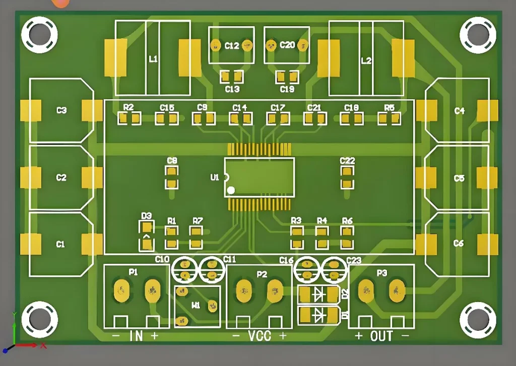
Before connecting the jack, you first need to design the layout of the circuit board. Reserve enough space for the jack and determine its distance from other components. The pins of the jack need to be correctly connected to the pads on the PCB so that they can be soldered smoothly. Reasonable layout can effectively reduce signal interference and noise. For audio circuits, long-distance signal transmission should be avoided as much as possible when wiring. - Solder the jack pins
Place the mono input jack in the predetermined position and ensure that its pins can be aligned with the pads on the PCB. Use a soldering iron to solder each pin to the corresponding pad. Usually, a mono jack has three pins:
Signal pin: The input terminal that receives the audio signal, usually connected to the input terminal of the audio amplifier. The signal pin is usually the central pin of the jack, which is connected to the signal output terminal of the external audio device.
Ground pin: The ground terminal, used to provide a common reference potential for the signal. The ground pin is usually one of the outer pins of the jack, which is connected to the ground of the PCB.
Power pin (if necessary): Some jacks may have an additional power pin for providing power to external devices. If your circuit design requires power supply, this pin is usually connected to the power line.
- Check the welding quality
After soldering, use a multimeter to check whether each solder joint is firm and confirm that there is no short circuit. Make sure the soldering point is clear and clean, and avoid too much or too little solder, which may affect the stability of the electrical connection. Good soldering quality is crucial to the stability of the circuit. - Connect the cable
Depending on the design requirements, it may be necessary to connect a cable to the mono input jack. Use a suitable cable to transmit the signal from the jack to other circuits. Make sure the cable is securely connected to avoid loose or poor contact. You can also use different types of plugs to accommodate different devices and interfaces. - Test the circuit
After making all the connections, power on the circuit to test it. Use an audio source (such as an audio player or microphone) to connect to the jack to check whether the signal can be transmitted normally. Make sure the audio output is clear and there is no noise or distortion. If there is a problem, check whether the connection is firm and whether there is a problem with the solder joint. When testing, you can use an oscilloscope to detect the signal waveform to ensure the quality of the signal.
Common problems and solutions
When connecting the PCB mono input jack, you may encounter some common problems. Here are some possible situations and corresponding solutions:
- Unclear signal or noisy
If the audio signal is unclear or noisy, it may be due to poor soldering or poor ground contact. Check the solder joints to make sure all connections are firm. You can also try to add filter capacitors to reduce signal noise. Using a proper ground layout can also reduce interference. - Poor contact of the jack
If the jack is not inserted stably or has poor contact, it may be due to insufficient soldering or poor jack quality. Re-solder the pins to ensure good contact between the jack and the pad. If the jack itself is of poor quality, consider replacing the jack. - Power supply problem
If the mono input jack used has a power pin and the power cannot be supplied normally, it may be due to insufficient power supply voltage or power pin welding problems. Check the power supply line to ensure that the power supply voltage is stable. If the power supply line is too long or the current is too large, it may also cause voltage drop, and the power supply design needs to be adjusted appropriately.
Summary
How to connect the PCB mono input jack is a very important step in audio circuit design. By correctly selecting the jack, designing the PCB layout, and ensuring that the soldering is firm, you can ensure that the audio signal can be transmitted stably.
Through the introduction of this article, I believe that everyone has a deeper understanding of connecting the PCB mono input jack. In actual design, paying attention to details and quality control can improve the stability and audio performance of the circuit. If you encounter problems, you can usually find and solve the problem by checking the soldering quality and connection method.
In future projects, mastering the skills of how to connect the PCB mono input jack will make you more handy in audio equipment design.


