As electronic devices continue to develop towards miniaturization, lightness, and multi-function, the limitations of traditional rigid circuit boards and flexible circuit boards have gradually emerged, and they cannot fully meet the complex needs of modern precision electronics. Against this background, PCB Flex Rigid (Rigid-Flex PCB) came into being. It combines the stable structure of rigid circuit boards with the bendable characteristics of flexible circuit boards, and has become an indispensable key component in high-end electronic design.
This article will systematically popularize and technically explain Rigid-Flex PCB from multiple aspects such as structural principles, design considerations, manufacturing processes, application scenarios, and development trends to help readers fully understand this increasingly important type of PCB.
What is a flexible rigid board?
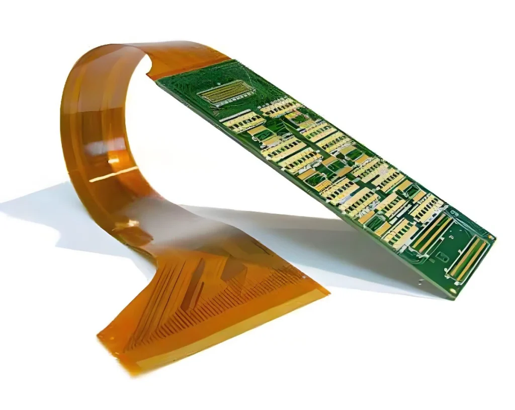
As the name suggests, a flexible rigid board is a composite circuit board composed of a flexible circuit board (FPC) and a rigid circuit board (RPCB) through pressing and other methods. Its biggest feature is that it can have both rigid and flexible structural properties in one circuit board, maximizing space utilization and minimizing mechanical connections.
Generally speaking, the structure of a flexible rigid board includes multiple rigid board layers, an intermediate flexible layer, a cover film, an adhesive, etc. The flexible part usually undertakes the connection and dynamic bending functions, while the rigid area is used to install components or provide structural support.
Structural principle and classification method
Basic structural composition
A standard Rigid-Flex PCB usually includes the following layers:
Flexible circuit layer: using polyimide (PI) material, with good bending performance;
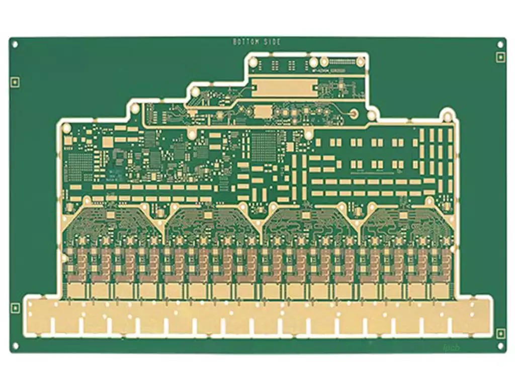
Rigid circuit layer: using glass fiber reinforced epoxy resin (FR4) as the base material;
Adhesive layer and insulating layer: connecting different structural layers to ensure electrical isolation;
Coverlay: protecting the flexible area from pollution and wear;
Through hole (PTH) and blind buried hole: realizing electrical connection between multiple layers.
Classification method
According to different structures and application requirements, Rigid-Flex PCB can be divided into the following categories:
Single-sided rigid-flex board: only one layer of flexible circuit is combined with the rigid layer, suitable for simple connection.
Double-sided rigid-flex board: the flexible layer has double-sided wiring to improve wiring density.
Multi-layer rigid-flex board: complex structure, suitable for high-end equipment.
Symmetrical and asymmetric structures: Depends on how the flexible and rigid layers are distributed on the structure.
This diverse structure makes the flexible-rigid combination board highly adaptable in meeting different engineering requirements.
Design points and engineering considerations
In the design process of Rigid-Flex PCB, it is necessary to consider both mechanical performance and electrical performance stability. Here are a few key considerations:
Principles of bending area design
As an active area, the flexible area should avoid the following problems when designing:
90° sharp angles cannot be designed, and smooth transitions should be used;
Avoid arranging too many vias in the bending area;
The width of the bending area should be kept consistent as much as possible to avoid local force concentration;
It is recommended to add ribs or reinforcement plates to improve reliability.
Routing rules and impedance control
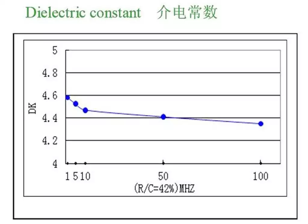
Since the dielectric constant of flexible materials is different from FR4, the impedance value must be recalculated when designing routing to avoid reflection and interference of high-speed signals at the interface.
Use differential pair wiring;
Strengthen EMC design to prevent the flexible area from becoming an antenna;
Set impedance matching points in the transition area from rigid to flexible.
Mechanical structure and assembly coordination
Rigid-Flex PCB is often used for 3D assembly, so it is necessary to combine the parameters of structural engineering:
Consider the location of mounting screw holes and snap-on structures;
Reserve an appropriate bending radius;
Use finite element analysis tools to verify mechanical properties.
Manufacturing process and its technical challenges
The manufacturing process of Rigid-Flex PCB is far more complicated than that of ordinary rigid boards or FPCs, and mainly includes the following steps:
Raw material preparation and lamination
FR4 sheets, PI films, cover films, adhesives and other materials need to be prepared, and vacuum hot pressing is used to complete the bonding between layers.
Drilling and electroplating
The vias and blind holes of the multi-layer structure need to be electroplated after CNC precision drilling to form metallized channels. The key technologies include:
Control drilling accuracy to prevent offset;
Select appropriate chemical copper plating solution to ensure the uniformity of copper in the hole.
Laser cutting and forming
For flexible areas and complex edge structures, CO₂ or UV lasers are required for contour cutting to improve accuracy and reduce material stress.
Surface treatment process
Depending on different application requirements, ENIG (gold-nickel), OSP, immersion tin and other processes can be selected to improve weldability and conductivity.
Advantage analysis: Why choose Rigid-Flex PCB
Although the application cost of Rigid-Flex PCB is higher than that of traditional board type, it brings obvious system-level advantages:
Reduce wiring and interfaces
Connecting multiple rigid modules through embedded flexible areas eliminates components such as wiring and connectors, reduces failure points, and improves reliability.
Save space and weight
Particularly suitable for portable devices, achieving higher functional density in a small space.
Improve seismic performance
Because the flexible part has shock absorption ability, it can maintain good electrical contact in a dynamic environment.
Reduce assembly process and cost
The integrated structural design simplifies the product assembly process and reduces manual plug-in steps.
Typical application scenarios
Due to its unique advantages, flexible-rigid boards are widely used in the following high-tech fields:
Smart wearable devices: such as smart watches, health bracelets, etc.;
Aerospace electronics: used for flight control units, navigation modules;
Medical devices: including ECG monitoring patches, endoscope control modules;
Industrial automation: high-speed cameras, sensor modules;
Consumer electronics: folding screen mobile phones, VR/AR devices, etc.
Quality inspection and reliability verification
After the production of Rigid-Flex PCB, multi-dimensional inspection must be carried out to ensure its stability and reliability:
AOI automatic optical inspection: detection of pad and routing defects;
X-Ray inspection: observation of blind and buried via plating conditions;
Bending fatigue test: simulation of repeated bending in actual use;
Temperature and humidity shock test: verification of environmental resistance.
Most of these test standards refer to international specifications such as IPC-2223 and IPC-6013.
Future trends and innovation directions
With the development of 5G, artificial intelligence, and the Internet of Things, Rigid-Flex PCB will continue to evolve:
Ultra-fine line width and line spacing (Sub-50μm): Adapt to high-frequency and high-speed signal transmission;
High multi-layer stacking (>10 layers): Improve wiring density and functional integration;
Embedded component design: Directly encapsulate some chips inside the PCB;
Green environmentally friendly materials: Comply with RoHS and REACH standards to reduce environmental burden;
Automated assembly support: Collaborative optimization with robots and 3D placement equipment.
Summary
As a bridge connecting rigidity and flexibility, structure and function in the electronics industry, the flexible rigid board not only changes the layout of electronic products, but also provides more innovation space for engineering design. Although its manufacturing threshold and cost are relatively high, it has irreplaceable advantages in reliability, space utilization, and seismic resistance.
Facing the future trend of high integration and intelligence, Rigid-Flex PCB will undoubtedly play an irreplaceable role in more key applications. For engineers engaged in PCB manufacturing or electronic design, mastering the design and process capabilities of this circuit board has become one of the core competitiveness that must be possessed.