In the modern electronics industry, schematic diagram of pcb are an indispensable and important part of the circuit design and manufacturing process. Whether you are a professional engineer or an electronic design enthusiast, you need to know how to draw and interpret circuit board schematics.
As the “language” of circuit design, this drawing plays a key role in bridging the design of electronic circuits and the actual production of circuit boards.

What is a circuit board schematic?
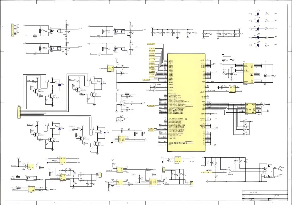
A circuit board schematic is a technical drawing that shows the functional relationship and connection method of each component in a circuit. It uses standardized symbols and connections to represent the design ideas of the circuit, so that designers and manufacturers can clearly understand the composition and working principle of the electronic system. The schematic is not only the basis of circuit design, but also an indispensable and important tool in subsequent circuit debugging, testing and repair.
The role schematic diagram of pcb
Design basis
When developing electronic equipment, the circuit board schematic is the starting point of the design. By drawing a schematic, engineers can determine the function of each component and its position in the circuit. This visual design method can help designers understand the working logic of the circuit system more intuitively.
Manufacturing guidance
The schematic provides guidance for the subsequent circuit board layout design. The design of PCB (printed circuit board) needs to be laid out and wired according to the circuit board schematic to ensure that the electrical connection between each component is accurate.
Debugging basis
During the circuit debugging process, the schematic diagram is a key tool for locating and analyzing problems. By comparing the schematic diagram, engineers can quickly find the fault point and repair it.
Maintenance reference
When an electronic device fails, the schematic diagram provides a clear reference for maintenance personnel, making troubleshooting more efficient.
Knowledge transfer
The circuit board schematic diagram can be used as part of the technical documentation to help other members of the team understand the circuit design. For large projects, good schematic design can promote the transfer of knowledge and reduce communication costs.
Components of circuit board schematics
Component symbols
Each electronic component in the schematic diagram has a corresponding symbol, such as resistors, capacitors, diodes, and triodes. These symbols are internationally standardized to ensure the universality of the design drawings.
Connecting lines
Connecting lines are used to represent electrical connections between components. In the schematic diagram, intersecting lines, nodes, and branches need to be drawn according to certain rules to avoid ambiguity.
Marking information
Each component usually comes with parameter markings, such as the resistance value of the resistor and the capacity of the capacitor. This information is the basis for component selection and procurement.
Reference number
Each component has a unique number in the schematic, such as R1, C2, etc., which is used to distinguish different components and facilitate search.
Power and ground line identification
The location of the power and ground lines is usually clearly marked in the schematic. These are the basis for the normal operation of the circuit and require special attention during design.
How to draw a circuit board schematic
Clear circuit requirements
Before drawing a schematic, the designer needs to clarify the functional requirements of the circuit. For example, whether it is necessary to implement functions such as signal amplification, power conversion or data processing.
Choose a design tool
There are many professional schematic design software on the market, such as Altium Designer, OrCAD, KiCad, etc. These tools provide rich component libraries and automation functions to improve drawing efficiency.
Determine the circuit structure
Design the overall structure of the circuit according to the requirements, including the connection relationship between the main components and modules.
Draw component symbols
Select the appropriate component symbols in the design software and place them in the drawing, while ensuring that their position and direction are reasonable.
Connect components
Use connecting lines to connect the components according to the circuit logic, and ensure that the connection points of each line are accurate.
Add annotations and numbers
Add necessary parameter annotations and reference numbers to each component for subsequent identification and use.
Perform verification and simulation
After completing the preliminary design, you can use the simulation function in the design software to test the circuit to ensure that its function meets expectations.
Precautions for circuit board schematics
Follow standards
When drawing schematics, you need to follow international or industry standards, such as the relevant specifications of IEEE and IEC. Standardized design can improve the versatility and readability of drawings.
Avoid crossing lines
When possible, minimize the crossing of lines to avoid increasing the difficulty of reading and understanding.
Clear annotations
All components and connection points should be clearly labeled to avoid ambiguity.
Modular design
For complex circuits, a modular design method can be used to decompose the schematic into multiple functional modules for easy management and maintenance.
Proofreading and optimization
After the design is completed, the schematic needs to be fully proofread to check whether there are logical errors or omissions, and optimize according to actual needs.
The relationship between circuit board schematics and PCB design
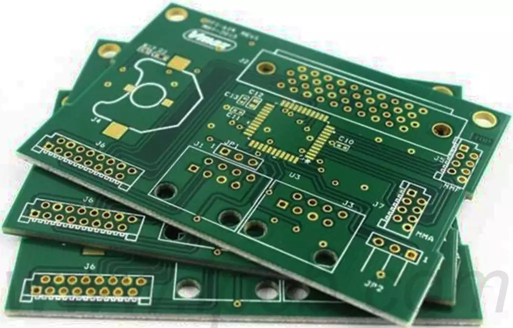
The circuit board schematic is the premise and basis of PCB design. Through the schematic, designers can transform abstract circuit concepts into specific PCB layouts. In the actual design process, each component in the schematic will correspond to a specific pad or pin on the PCB, and the connecting wire will be converted into copper foil routing.
Modern PCB design software usually supports the linkage function between schematics and PCB. For example, designers can directly generate the initial layout of the PCB through the schematic and update it synchronously in subsequent designs. This method not only improves design efficiency, but also reduces manual operation errors.
Future development of circuit board schematics
Intelligent design
With the development of artificial intelligence technology, schematic design has also begun to develop in the direction of intelligence. Future design tools may automatically generate schematics based on user input requirements and provide optimization suggestions.
Cloud collaboration
The popularity of cloud computing technology allows designers to share and collaborate on schematics in the cloud, making it convenient for multiple teams to jointly complete the design of complex circuits.
Multi-physics simulation
Schematic design software is gradually integrating multi-physics simulation functions, which can comprehensively analyze circuit performance during the design stage. For example, simulate the thermal effects, signal integrity and electromagnetic compatibility of circuits.
Virtual reality technology
Virtual reality technology is expected to be applied to schematic design, helping designers to understand and optimize circuit structures more intuitively.
Open design platform
Future schematic design tools may support open platforms, allowing users to create and share custom component libraries and design templates, thereby further improving design efficiency.
In-depth integration with manufacturing processes
Schematic design will be closely integrated with manufacturing processes, and designers can consider the limitations of the production process at an early stage, thereby reducing manufacturing costs and improving yields.
Collaboration between circuit board schematics and engineering teams
Circuit board schematics play a bridging role in cross-team collaboration. After R&D engineers draw schematics, hardware engineers can make PCB layouts based on schematics, while production engineers design production processes based on PCBs.
At the same time, software developers may also need schematics to understand hardware interfaces and optimize the overall performance of the system. In large-scale projects, schematics can improve communication efficiency between teams and ensure unified design goals.
The teaching significance of circuit board schematics
For students majoring in electronics, learning circuit board schematics is an important step in getting started. By reading and drawing schematics, students can master basic circuit knowledge and learn how to apply theoretical knowledge to practical problems.
At the same time, analyzing classic circuit schematics is also an effective way to cultivate innovative ability. By reviewing classic designs, students can understand the design logic and gradually form their own design thinking.
The combination of schematics and analog circuits and digital circuits
Analog circuits and digital circuits occupy a core position in electronic design, and schematics are the key to the integration of the two. In analog circuits, schematics need to accurately represent the parameters of components such as amplifiers, filters, and signal processing modules, while digital circuits focus more on the definition of logic gates, circuit timing, and interface protocols.
Through schematics, designers can perfectly combine the characteristics of analog circuits and digital circuits to design high-performance hybrid circuit systems.
The role of open source schematics in promoting the industry
In recent years, the rise of open source hardware communities has promoted the popularity of schematic design. Many designers have made schematics public on open source platforms, allowing beginners and small teams to refer to existing designs, thereby lowering the development threshold. Taking Arduino and Raspberry Pi as examples, their open source schematics provide basic templates for countless developers and promote the explosive growth of hardware innovation.
How to evaluate the quality of circuit board schematics
A high-quality circuit board schematic not only needs to be beautiful and clear, but also needs to be logically rigorous and functionally complete. When evaluating schematics, you can start from the following aspects:
Structural logic: whether the circuit module division is reasonable, and whether the overall design meets the expected functions.
Marking specifications: whether the component parameters are complete and clear, and whether they meet industry standards.
Readability: whether the lines are clear, whether unnecessary intersections and complex paths are avoided.
Reliability test: whether it has passed simulation verification, and whether it can run stably in actual applications.
Innovative design trends in schematics
With the continuous development of technology, the design of circuit board schematics has also shown more and more innovative trends. For example, modern design tools support the embedding of programmable logic modules in schematics, allowing designers to consider software functions in the design stage.
At the same time, the introduction of new components has also promoted changes in schematic design, such as the application of microelectromechanical systems (MEMS) and flexible electronic components, making schematic design more diverse and complex.
The cultural significance of circuit board schematics
In the eyes of many engineers, circuit board schematics are not only technical tools, but also the embodiment of design art.
A perfect schematic not only shows the technical ability of designers, but also reflects their understanding and love of electronic disciplines. Many designers will even save the carefully drawn schematics as a souvenir, as an important milestone in their technical career.
Summary
As an important part of electronic design, schematic diagram of pcb have a profound impact on the entire circuit design and manufacturing process. Through standardized drawing and reasonable use, designers can significantly improve the performance and reliability of circuits.
With the continuous advancement of technology, circuit board schematics will also develop in the direction of intelligence and multi-functionality, bringing more innovation and possibilities to the electronics industry.


