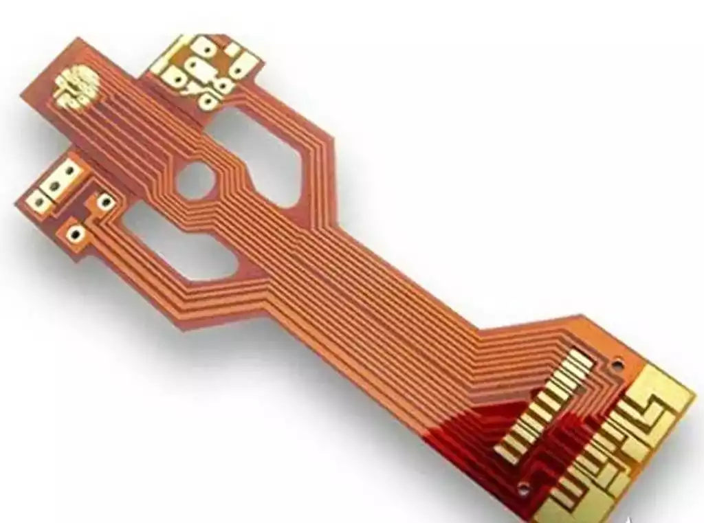
Flexible PCB is carefully designed to cope with bending requirements, and their bend radius is a core parameter that ensures their functionality and durability. This parameter determines the extent to which the PCB can be bent safely without damage.
The bending radius of a flexible PCB is influenced by a number of factors, the main ones being the thickness of the material, its rigidity, the distribution of layers and the location of the rigid areas. To ensure optimal performance of flexible PCBs, the following guidelines should be followed during design:
Avoid designing sharp turns (90-degree angles) and prioritize the use of smooth gradient curves.
Utilize PCB cutouts to reduce the required bend radius.
Appropriately reduce the thickness of copper wires to enhance the bending capability of the PCB.
When a flexible PCB is bent, the two sides of the centerline are subjected to different types of stresses. The inner surface is under pressure, while the outer surface is under tension. The amount of stress is directly related to the thickness of the flexible PCB and the radius of the bend. Excessive stress can lead to delamination and cracking of copper foils on FPC flex circuit boards. Therefore, during the design process, the lamination structure of the FPC flexible PCB should be reasonably planned to ensure that the lamination structures at both ends of the centerline of the bending surface are as symmetrical as possible. In addition, according to different application scenarios, the minimum bending radius should be precisely calculated and determined.
The main factors affecting the calculation of the bending radius of a flexible PCB include:
Substrate thickness: Thick substrates usually require a larger bend radius because they are less flexible. On the contrary, thin substrates are easier to bend and therefore have a relatively small bending radius. According to the specific application requirements of the flexible PCB, the appropriate substrate thickness should be selected to balance flexibility and reliability.
Number and Type of Copper Layers: Copper layers provide connections to the circuitry and also increase the rigidity of the board. If a flexible PCB contains copper layers, the bend radius needs to be increased in order to prevent damage to the copper wires or vias during the bending process. In addition, the type of copper (e.g., standard copper or high-temperature copper) also affects the flex PCB’s bending performance.
Flexibility of the cover material: The cover material is used as a protective layer for the flex circuit board and is designed to protect the copper layer and provide insulation. Its flexibility is affected by the composition and thickness of the material. Highly flexible cover materials allow smaller bend radii, while less flexible materials require larger bend radii to avoid breakage or delamination.
Overall design layout: Components close to the bending area may require a larger bending radius to ensure proper functioning and avoid damage. Therefore, careful planning of routing and component placement is required to avoid sharp corners or sharp turns, which can lead to stress concentrations and failures.
The main methods for calculating the bend radius of a flexible PCB are:
Reference to the IPC-223 standard, which provides guidelines for calculating the bend radius based on the thickness and number of layers of a flexible PCB. The standard takes into account the various physical and mechanical stresses to which the flexible PCB is subjected during the bending process.
Calculations are made using empirical formulas such as R = T x K, where R is the bending radius, T is the PCB thickness, and K is a constant related to the material properties. This formula provides a basis for the initial estimation of the bending radius and can be used as a starting point for further analysis and optimization.
The flexible layer is used as an inner layer inside the rigid part and can be used for conductor routing. In general, the minimum bend radius of a flexible PCB is usually between 1mm and 6mm. Adequate reliability under dynamic bending conditions can only be ensured when using single- or double-layer flexible PCBs.