PCB circuit boards play a pivotal role in electronic equipment, not only carrying various types of electronic components, but also responsible for their precise connection to ensure stable and reliable operation of the circuit. So, in the design and production of PCB circuit boards, how to connect components on pcb?
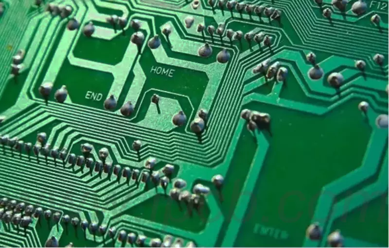
The most common method of connecting PCBs to each other is soldering. Through soldering, conductive materials such as tin can be melted to firmly bond the electronic components to the wires on the PCB. Before soldering, we need to prepare a soldering iron, solder wire and tin dip. The soldering iron is heated to a suitable temperature, then dipped into the soldering wire and tin soaking liquid and applied to the components and wires to be connected. Afterwards, the soldering iron gently touches the solder to make it melt quickly, and then quickly remove the soldering iron. Once the solder has cooled and solidified, the soldering is complete.
However, in some special cases, soldering may not be suitable. For example, for some delicate electronic components, high temperature soldering may not be appropriate. In this case, we can choose to use plug-in connectors. This type of connector usually consists of two parts: a plug and a socket. The plug is fixed to the electronic component, while the socket is fixed to the PCB circuit board. When a connection is required, the plug is simply inserted into the socket for a quick connection of the circuit. Compared with soldering, plug-in connectors are easier to operate and can be reused.
In addition, when some lines need to cross a long distance between the PCB circuit board, we can also use the wire and clip connection. Specific operations are as follows: first, strip the wire ends of a small section of insulation, the bare wire into the clamp and firmly clamped. Then, connect the other end of the clip to the PCB board on the wire. This type of connection is suitable for temporary connections or lines that require frequent replacement.
In order to improve the stability and reliability of the line connection, we can also take some auxiliary measures. For example, after soldering or plugging is completed, heat shrink tubing can be used to fix the line connection. Heat shrink tubing is a heat-shrinkable plastic sleeve that shrinks when heated and tightly wraps around the line connection, providing additional protection and retention. Additionally, wire retaining clips can be used to securely fasten the wiring to the PCB to prevent wiggling or disconnection of the wiring.
We also need to pay attention to the following points in the wiring arrangement of PCB components:
(1) In the printed circuit, should avoid cross circuit. For lines that may cross, you can use the “drill” or “winding” method to solve the problem. That is to say, let a certain lead from other resistors, capacitors, transistors under the gap through, or from the possible cross of a certain lead end bypass. In special cases, if the circuit is more complex, in order to simplify the design, you can also allow the use of lead spanning to solve the cross-circuit problem.
(2) Components such as resistors, diodes, and tubular capacitors are mounted in two ways: vertically and horizontally. Vertical mounting means that the component body is mounted and soldered perpendicular to the circuit board, and this method saves space. Horizontal mounting, on the other hand, involves mounting and soldering the component body parallel and close to the circuit board, which has better mechanical strength. Due to the difference between the two installation methods, the hole spacing of the components on the printed circuit board will also be different.
(3) The grounding points of the same level of circuitry should be as close as possible, and the power supply filter capacitors of this level of circuitry should also be connected to the grounding points of this level. In particular, the base of the transistor and the emitter of this level of grounding can not be too far apart, otherwise due to the two grounding points between the copper foil is too long may cause interference and self-excitation. Using this “one-point grounding method” of the circuit is more stable, less likely to produce self-excitation phenomenon.
(4) the connection of the total ground should follow the high-frequency, medium-frequency, low-frequency order, and in accordance with the principle of weak power to strong power arrangement. Do not connect randomly, the connection line between the level and the level can be a little longer, but also to follow this principle. Especially inverter head, regeneration head, FM head and other parts of the grounding line arrangement requirements are more stringent, improper connection may lead to self-excitation phenomenon and can not work properly. High-frequency circuits such as the FM head often use a large area surrounded by ground to ensure a good shielding effect.
(5) Strong current leads (such as public ground, amplifier power leads, etc.) should be as wide as possible in order to reduce the wiring resistance and voltage drop, and reduce the self-excitation phenomenon generated by parasitic coupling.
(6) The high impedance alignment should be as short as possible, while the low impedance alignment can be a little longer. This is because high impedance alignments are prone to emitting and absorbing signals, which may lead to circuit instability. Power lines, ground lines, base alignments without feedback elements, and emitter leads are all low impedance alignments. For example, the base alignment of the emitter follower and the ground of the two channels of the recorder should be laid out separately, each forming one way until the end of the amplifier and then combined. If the two ground lines are not properly connected, crosstalk will easily occur, reducing the degree of separation.
Through reasonable line connection and component installation skills, we can ensure the stability and reliability of the PCB circuit board, improve the performance and life of electronic equipment. In practical applications, appropriate connection methods and installation techniques should be selected according to specific needs and component characteristics to achieve the best circuit connection results.