What is resistance circuit? A resistance circuit is a circuit consisting solely of a power source and a linear resistor, and is the degree of obstruction encountered by the flow of current through the circuit, which is usually measured in ohms (Ω).
A distinctive feature of resistance circuits is that the electrical energy is converted primarily to internal energy, which is usually expressed as heat. Resistance circuits are applicable to both DC and AC circuits. The main function of a resistor in a circuit is to limit the flow of current and ensure that other electronic components in the circuit are not damaged by excessive current. In a resistive circuit, electrical energy is converted almost entirely to internal energy and very little to other forms of energy. Resistors are able to absorb energy from the power source and convert it almost entirely into heat.
For a purely resistive circuit, the phase angle between the current and voltage is zero, which means that the voltage and current are at the same frequency and in phase, exactly as described by Ohm’s law. Purely resistive circuits usually do not contain inductive or capacitive components, or the effect of these components on the circuit is negligible.
Equivalent transformations of circuits:
1. Two-terminal circuits (networks)
Any complex circuit with two terminals leading outward and the current flowing from one terminal is equal to the current flowing from the other terminal is called a two-terminal network (or one-port network).
2. The concept of two-terminal circuit equivalence
Two two-terminal circuits, the port has the same voltage, current relationship, they are said to be equivalent circuit.
Circuit equivalent transformation conditions: the two circuits have the same VCR; circuit equivalent transformation object: unchanged external circuit A in the voltage, current and power; (that is, the external equivalent, the internal is not equivalent); circuit equivalent transformation purpose: to simplify the circuit, easy to calculate.
Resistance parameters:
Nominal Resistance
Nominal resistance refers to the resistance value labeled on the resistor. The unit of resistance value is ohm, expressed in “Ω”. Some also use thousands of ohms (kΩ), megohms (MΩ) said. 1MΩ = 1000kΩ, 1kΩ = 1000Ω .
Power Rating
Power rating refers to the maximum power that a resistor can withstand in AC or DC circuits when working under specific conditions for a long period of time. The power rating of a resistor has a nominal value and is generally divided into 1/8W, 1/4W, 1/2W, 1W, 2W, 3W, 4W, 5W, 10W and so on. For example, 1/4 W is the power rating of this resistor, which is 0.25W.
If the current through the resistor is too high and exceeds the power rating of the resistor, the resistor will heat up severely until it burns out. Therefore, when selecting a resistor, consider the resistance value as well as the power rating of the resistor. For example: the power supply voltage 5V, the load bulb rated voltage 4V, 300MA, when selecting the current limiting resistor, it can be seen that the voltage drop in the circuit needs to be 1V, the current is 300MA, so the choice of the resistance value should be 1V divided by 0.3A = 3.33Ohm, the resistor consumes the power of 1V multiplied by 0.3A = 0.3W. After determining the resistance value of 3.33Ohm, but also to select the power of 1/2W and above. Resistor.
Allowable Deviation
The actual resistance value of a resistor can not be exactly equal to the nominal resistance value, there will be more or less deviation between the two, the deviation of the allowable range is called the allowable deviation of the resistor. A resistor with a small allowable deviation has a higher precision of resistance value. The allowable deviation of common resistors is ±5%, ±10%, ±20%, while the allowable deviation of high-precision resistors is ±1%, ±0.5%.
Resistors have the following four main roles in the circuit:
1. Current limiting; resistors in the circuit to limit the passage of current, the same voltage, the larger the resistance value the smaller the current.
2. Voltage reduction; current flows through a resistor, which produces a voltage drop at both ends of the circuit. For the same current, the larger the resistor value, the larger the voltage drop.
3. Voltage divider; different resistors combined in a circuit can easily form a voltage divider to realize voltage division.
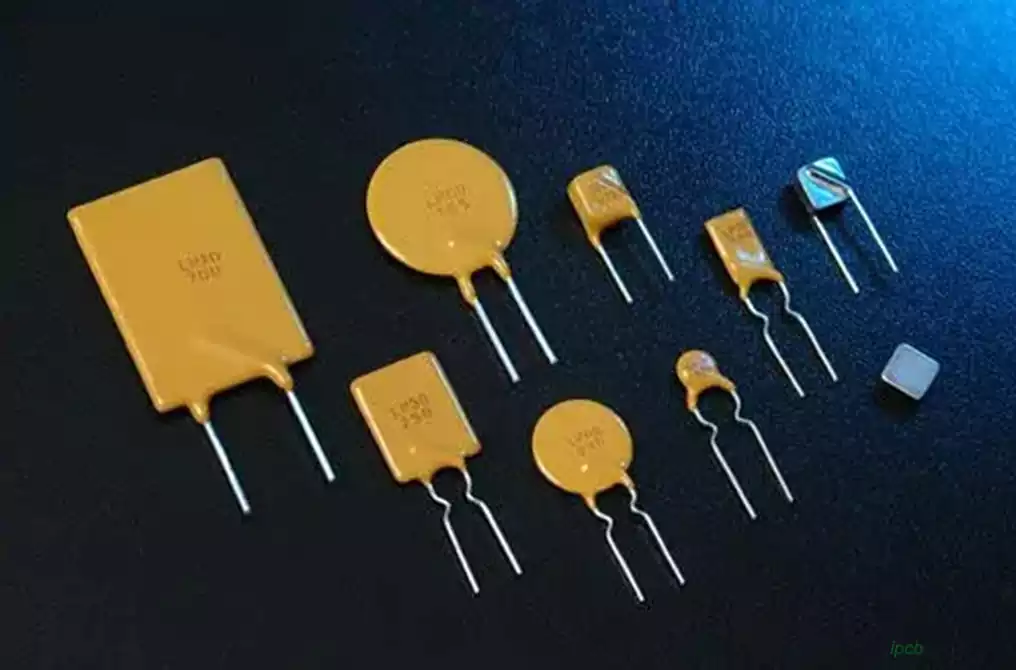
4. Protection; varistors are mainly used for surge protection and overvoltage protection; fusing resistors can play a role in fusing protection.
Resistive circuits occupy an indispensable position in electronics, whether as a basic current obstruction device, or a special functional element in complex circuit systems, resistors play a vital role. Their unique properties, such as the conversion of electrical energy into internal energy, limiting current flow, and realizing functions such as voltage dividing, make resistors have a wide range of uses in circuit design and applications.