Description
Modern electronics have come a long way with the advent of flexible PCB technology. They are present at the heart of many sensitive and delicate electronics. Even your smartphone, camera, laptop, calculator, and many electronic gadgets are using this technology.
What is a flex pcb?
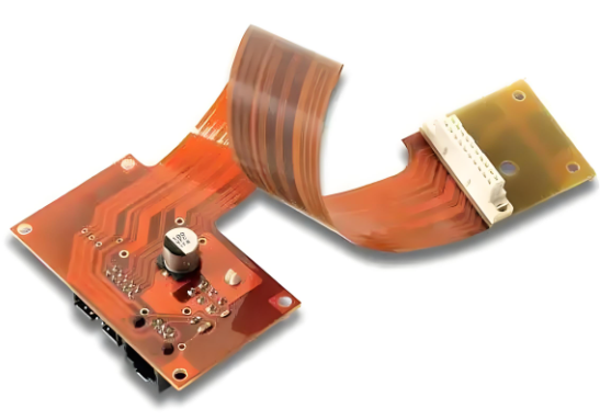
Flex pcb fabrication is made of a base substrate material of polyimide. This material is both natural and synthetic and is used in various industries such as automobiles, clothing, etc. The compactness and high electrical connection density of flexible circuits provide us with considerable weight, space, and savings compared to traditional rigid printed circuit boards. When connected to the right application, this technology can reduce the overall cost of electrical interconnections by up to 70% and reduce wiring usage by up to 75%.
Step 1: Flexible PCB Construction
This is the main stage where the main focus is on saving the base material. The main material used for flexible circuits is polyimide. This material is expensive compared to FR-4 and needs to be used correctly. To use polyimide properly, you need to use nesting techniques to keep the circuits as close as possible.
Prototype PCB manufacturing includes the following processes:
Looping: It is acceptable to add a small amount of additional material beyond the designer’s limit. This additional material is called a service loop and enables service length and circuit assembly.
Sizing the conductors: It provides the most flexibility, so you need to choose the thinnest copper, especially when you want to use the circuit for dynamic applications.
Etching: This process is used to compensate for any isotropy loss during the manufacturing process. The line width loss during this process is almost twice the thickness of the copper foil. Several factors affect the line width, such as different types of copper, etching masks, conductors, etc.
Routing: The routing of the conductors can be done easily. Just fold the bends in a vertical position. This will improve folding and bending by reducing stress.
Ground plane: If the electrical distribution is sufficient, a cross-hatched ground area is created. This helps to increase the flexibility of the circuit by reducing the weight of the board,
Step 2: Starts with conductor spacing and width
Polymer films require a standard conductor width, which is 375 microns. Meanwhile, nominal polymer thick films and silver-based polymer films carry the required percentage of circuit current. The diameter of the holes in a flexible PCB may vary depending on the design and application.
Hole Size: Manufacturers can create small holes and also have flexibility in PCB layout to tilt them. With advanced technology, you can make the hole as small as possible (i.e. 25um).
Corner Fillet: Corner fillet is a technique where you multiply the area of the pad and divide the stress. All pads and pad termination points on flex circuits require corner fillets. Plated through holes are suitable for creating reliable solder joints.
Button Plating: Here, you can create alternative plated through holes. Today, manufacturers use copper to prepare through holes and vias.
Step 3: Focus on Physical Constraints
Adhesive Film: Suitable for dynamic flex circuit applications as it consists of raw materials. Adhesive Film is mainly used for recoating custom PCBs.
Screen Printable Liquid Overcoat: Screen Printable Liquid Overcoat is portable and is usually used for thick polymer films.
Imagine Liquid and Thin Film Polymer: It is the most advanced recoating method and has some amazing features such as:
Acts as a solder mask and prevents solder from forming circuit traces.
It protects the printed circuit from external and internal damage.
It prevents the circuit from being charged externally,.
Rigid PCB vs. Flex PCB: What’s the Difference?
While both rigid PCBs and flexible PCBs fulfill the same basic purpose of connecting electronic components of various devices, it is worth noting their many differences. Rigid and flexible PCBs are manufactured differently and have different performance advantages and disadvantages. Here are their unique properties and features.
- Base: Rigid boards connect electrical components using conductive tracks and other components arranged on a non-conductive substrate. This non-conductive substrate often contains glass, which gives it strength and thickness. Flexible PCBs also have conductive traces on a non-conductive substrate, but it uses a flexible substrate such as polyimide.
- Flexibility: The base of a rigid board enhances the strength and rigidity of the board. Dynamic flex PCBs, on the other hand, use a base that has flexibility because it can be bent to fit the desired application and folded into a variety of shapes.
- Conductors: Rigid circuits typically use electrolytic copper as the conductive material, but because flexible circuits can be folded and bent, manufacturers may use more flexible rolled annealed copper.
- Manufacturing Process: The solder mask application in rigid circuits is replaced by a process called coverlay or coverlay in flexible PCB manufacturing to protect the exposed circuitry of the board.
- Cost: Flexible circuits generally cost more than rigid boards. However, because flexible circuits can fit into compact spaces, manufacturers can make portable-sized products in consumer electronics, medical devices, space, and automotive applications, which are in high demand, generating more revenue and indirect savings for electronics manufacturers.
- Durability: While both types of PCBs offer a fair degree of durability, each performs differently. Rigid PCBs offer greater strength, while flexible materials enable PCBs to better absorb vibrations, dissipate heat, and withstand other environmental factors.
- Weight: The strength and thickness of rigid PCBs means they weigh slightly more than flexible PCBs, which are generally lighter. This is a beneficial feature for the electronics industry, which often manufactures small devices that require lighter components.
- Tolerance: Flexible PCBs are highly tolerant of high temperatures and extreme environments, so they are less likely to succumb to such stresses. In contrast, rigid PCBs have less electrical resistance, making them more susceptible to damage or deformation from heat, radiation, or chemicals.
- Design Complexity: For more basic consumer devices, such as toys or musical keyboards, rigid PCBs are a good fit. However, flexible PCBs are more complex to design, making them ideal for highly complex products.
What is a Rigid-Flex Board?
Rigid-Flex PCB design combines rigid and flexible board technologies. In most rigid-flex boards, the flexible circuit substrate layer is connected to one or more rigid boards internally, externally, or both, depending on the design specifications of the application. Typically, rigid-flex printed circuit boards are produced with flexible polyimide material on a copper-clad substrate that is connected to the rigid board. The layers of the flexible portion of the rigid PCB are often provided with filled vias to ensure interconnectivity between them.
Advantages
Rigid-Flex boards offer many advantages, including light weight, ease of assembly and repair, and enhanced reliability, performance, and flexibility of electronic devices.
Compact Size
Electronic devices are becoming smaller and more flexible. The versatility of rigid-flex PCBs allows them to bend and flex to fit smaller devices and properly connect miniature components. This miniaturization also makes them lightweight.
Improved Reliability
Since there are fewer solder joints and board-to-board connectors, there is also less chance of connection impedance. In addition, the attached rigid and flexible layers are firmly and reliably connected, ensuring fewer circuit failures.
Save Space
Since the flexible substrate has interconnected circuits built into it, there is more room on the rigid-flex PCB for routing. This makes the board suitable for applications with compact designs as they do not provide much space for wiring harnesses and high-profile connectors.
Reduced Costs
Although rigid-flex boards are more expensive than regular rigid PCBs, they are more cost-effective in terms of assembly expenses. Due to their smaller size and fewer connections, rigid-flex PCBs require less material for assembly. Fewer parts and connector components reduce the procurement and assembly costs of the final product and increase revenue. This means that rigid-flex PCBs significantly reduce the overall manufacturing cost of assembly and logistics.
Easy to Test
Automated testing can be easily performed on the interconnected subcircuits of rigid-flex PCBs. This testing enables manufacturers to eliminate connection issues before components are assembled, thus preventing unnecessary waste and expense.
Design Flexibility
The 3D design and multi-layer flexible circuits make rigid-flex PCBs highly flexible and able to fit into small devices. This way, devices are no longer limited to a specific PCB design like rigid boards, as rigid-flex boards can be bent into a variety of applications due to their impressive bend radius.
Resistant to High Temperatures and Harsh Conditions
This type of PCB can withstand high temperatures because polyimide with high thermal stability is used in its design. In addition, by combining the best features of rigid and flexible boards, it has considerable resistance to radiation, harmful oils and chemicals, as well as extreme shock and vibration, and other harsh industrial conditions. This makes it ideal for devices that may be subject to excessive movement and vibration during use.
Disadvantages
While rigid-flex boards have many advantages, they also have a number of disadvantages that manufacturers must carefully weigh before investing in them. Others have a long and difficult production process, so more money needs to be invested in materials and manpower to obtain a certain assembly speed, which incurs costs. If adjustments need to be made to the actual design during the testing phase, this is very difficult for rigid-flex boards because it may be necessary to return to the Gerber programming to correct the errors. This means increased expenditure and time because it actually requires redesigning the entire design. It is well known that it has a lower yield rate.
I believe that after reading this article, you have a deeper understanding of flexible PCBs and can also compare them with rigid-flex boards.