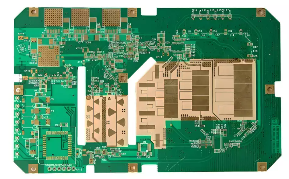
What is a coil on pcb? A coil on pcb is formed by winding wires into a spiral (or other geometric shape) to create an inductive element.The coil produces a magnetic field when an electric current is passed through it. According to Faraday’s Law of Electromagnetic Induction, a varying magnetic field induces a current in the surrounding conductors. This property makes coils particularly important in a variety of electrical applications.
Types of coils on pcb
- Transformer: A transformer is a device that transmits alternating current energy from one circuit to another, and it consists mainly of one or more coils and an iron core. Voltage converter converts alternating current of a certain voltage to another level of alternating current. Ordinary light industrial transformer for the first time and contact transformer is mainly used to change the AC voltage from 230 volts to 3, 6, 9, 12, 24 volts, etc., it is the most widely used kind of transformer.
- Inductors: Inductors are components that generate electromagnetic waves by changing the current through the coil. There are two most important features in inductors: internal impedance and inductance size. The main functions of inductors are filtering, tuning and storing electrical energy.
- Filters: Filters use a combination of coils and capacitors to eliminate clutter and interference in electronic devices. Filters are generally an essential component in electronic circuit design.
Classification of Inductive Coils.
There are many types of inductive coils with different classifications.
According to the wire center classification, it can be divided into hollow inductor coil, magnetic core inductor coil, iron core inductor coil and copper core inductor coil.
According to the installation of the form of classification, it can be divided into vertical, horizontal inductor coil.
According to the working frequency classification, it can be divided into high-frequency inductor coil, medium-frequency inductor coil, low-frequency inductor coil.
According to the use of classification, it can be divided into power supply filter coil, high-frequency filter coil, high-frequency current-blocking coil, low-frequency current-blocking coil, line deflection coil, field deflection coil, line oscillation coil, line linear correction coil, local oscillation coil, high-frequency oscillation coil.
According to whether the inductance is adjustable classification, it can be divided into fixed inductance coil, variable inductance coil, fine-tuning inductance coil.
According to the winding method and its structural classification, it can be divided into single-layer, multi-layer, honeycomb type, skeleton type and skeleton type inductor coil.
The design of inductor coil mainly involves the number of turns, wire diameter, winding method and the selection of core material. The selection of these parameters will directly affect the inductance, quality factor (Q) and applicable frequency and other performance indicators of the inductor coil.
Number of turns: The more turns, the more inductance, but also increase the coil resistance and reduce the Q value. Therefore, it needs to be weighed according to the actual needs.
Wire Diameter: The larger the wire diameter, the lower the resistance of the coil, but too large a wire diameter may increase the size and weight of the coil.
Winding method: The winding method has a great influence on the Q value and distributed capacitance of the coil. Reasonable winding method can improve the Q value and stability of the coil.
Core material: The choice of core material has a great influence on the inductance and Q value. Common core materials include ferrite, silicon steel and pomoloy.
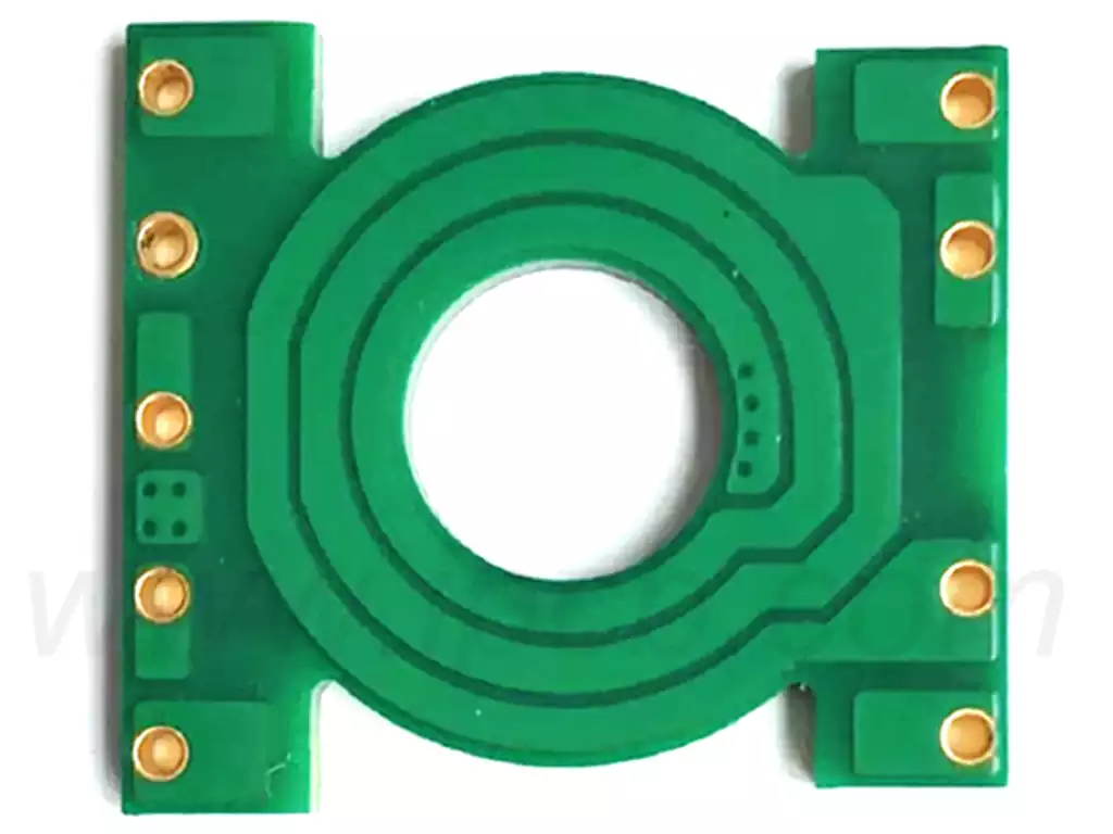
Circuit board coil production
After determining the design parameters, you can start making the inductor coil. The following points need to be noted during the fabrication process:
Select suitable insulating materials to ensure the insulation between turns of the coil and between the coil and the core.
Keep the accuracy of wire diameter, number of turns and winding method during the winding process to ensure the stable performance of the inductor coil.
Pay attention to the cleanliness of the winding environment to avoid the influence of dust and impurities on the coil performance.
According to the need to choose the right core, and appropriate core fixing, in order to prevent vibration or temperature changes on the performance of the inductor coil.
After fabrication, rigorous testing and adjustment is required to ensure that the performance of the inductor coil meets the design requirements.
Optimization of coil on pcb
After the production of the coil is completed, it can be optimized according to the actual application requirements to improve its performance. Optimization methods include:
Adjusting the number of turns, wire diameter and winding method of the coil on pcb to improve the inductance and Q value.
Selecting appropriate core materials and shapes to improve the frequency characteristics of the coil.
Vacuum impregnation of the coil to minimize the distributed capacitance and enhance insulation properties.
Apply advanced core materials and preparation techniques to improve the energy density and stability of the coil.
Heat dissipation is considered in the design to improve the reliability and service life of the coils.
Coil on pcb, as core components on circuit boards, play an indispensable role in circuits with their subtle design and unique electromagnetic characteristics. With the progress of science and technology, the performance of inductor coils will continue to be optimized, injecting new vitality into the development of electronic equipment.
