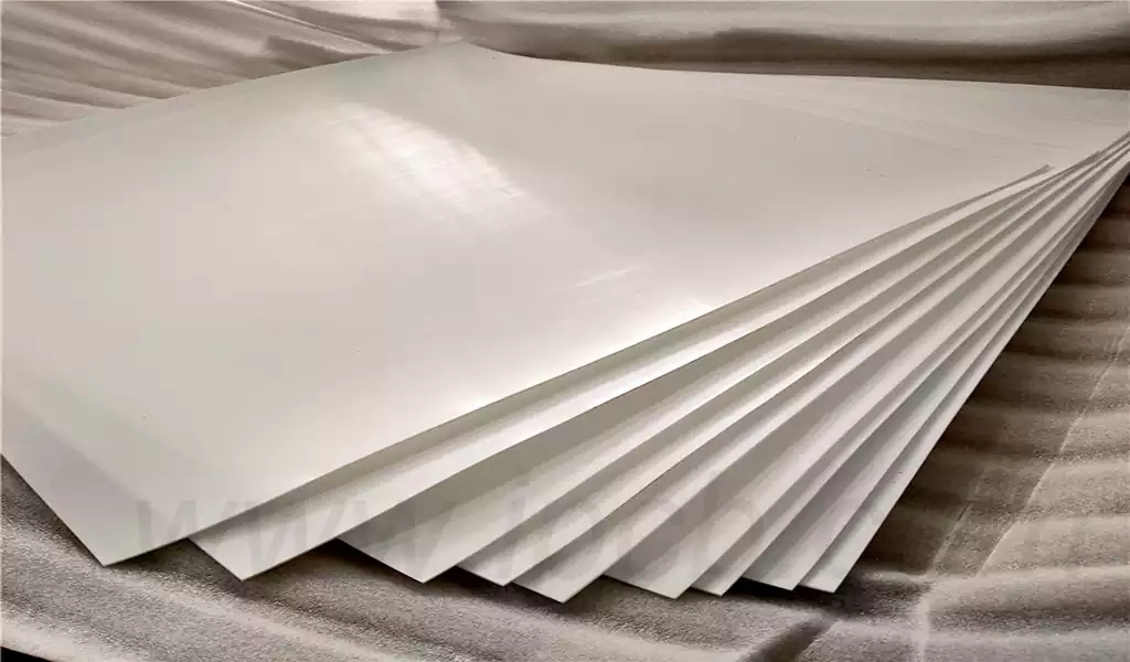
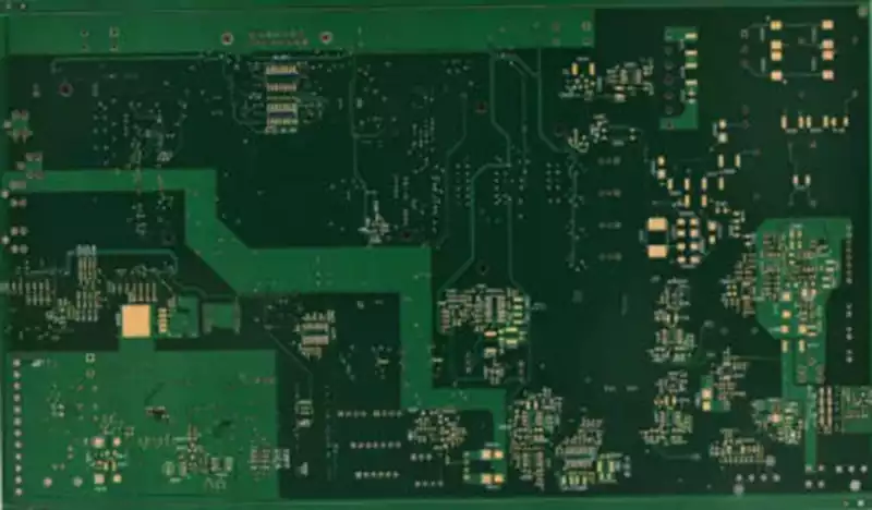
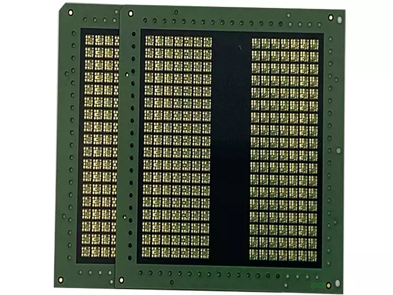
PCB board thickness usually refers to the overall thickness of the PCB, including the circuit layer, dielectric layer, and copper cladding layer. Thick pcb board are usually expressed in millimeters (mm), and common thicknesses include 0.6mm, 1.0mm, 1.6mm, 2.0mm, 2.4mm, etc. When designing a PCB, it is necessary to select the appropriate board thickness according to actual needs to ensure the performance and reliability of the PCB.
- Conventional thickness: 1.0mm, 1.6mm, 2.0mm
These thicknesses are usually used for general applications such as consumer electronics, smart homes, industrial control, etc. These applications do not require particularly high mechanical strength or conductivity, so conventional thickness PCBs can be used.
- Ultra-thin board thickness: 0.4mm, 0.6mm
These ultra-thin board thicknesses are usually used for lightweight and miniaturized electronic products such as smart watches, smart glasses, smart wearable devices, etc. These products require very light PCBs, so the use of ultra-thin PCB board thicknesses can meet the needs.
- High-strength board thickness: 2.4mm, 3.0mm
These high-strength board thicknesses are often used in some industrial and military applications, such as aerospace, rail transportation, military equipment, etc. These applications require PCBs to have high mechanical strength and durability, so using PCBs with high-strength board thickness can meet the requirements.
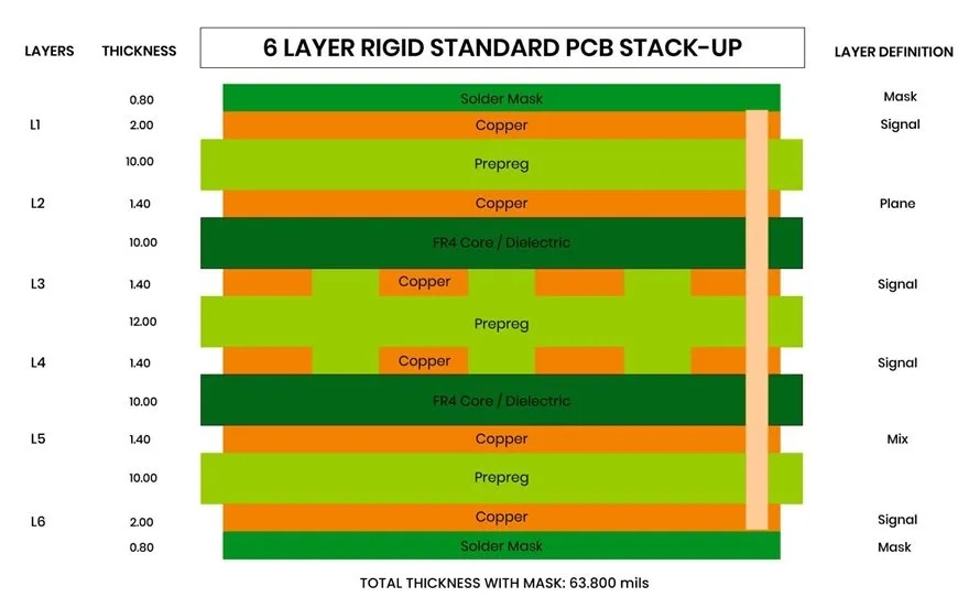
Factors affecting PCB thickness
- Copper thickness
The total thickness of the PCB is affected by the thickness of the copper layer it contains. Thicker copper layers (such as 2-ounce or 3-ounce copper) contribute more to the total thickness than thinner copper layers of 1 ounce. The thickness of the copper layer used is determined by the current that needs to pass through the circuit board.
- Substrate
The choice of substrate will significantly affect the thickness of the PCB board. Different materials have different thicknesses, for example, flexible printed circuit boards generally have thinner substrates compared to rigid PCB substrates. Common substrate materials such as FR-4 have standard thicknesses, but special materials may have unique thickness characteristics.
- Number of PCB layers
For single-layer PCBs, the thickness is smaller than that of multi-layer printed circuit boards. Standard thresholds for PCB thickness typically accommodate 2-6 layer PCBs. However, for PCBs with 8 or more layers, the thickness may not be within the standard range. Each additional layer adds to the total thickness of the PCB.
- Signal Type
The thickness of a PCB is affected by the type of signal it carries. For example, a PCB carrying high-power signals requires thicker copper layers and wider routing, which is much thicker than a board operating in a low-power environment. On the other hand, high-density boards with complex signals often use laser microvias, fine markings, and thin high-performance materials, making them traditionally thinner than other types of boards.
- Via Type
PCB via replay is essential for routing different layers of a board, allowing for more compact and efficient designs. Multiple types of vias are available for different applications, including through-holes, microvias, blind vias, and buried vias.
The selection and density of vias used in a PCB design will affect the required printed circuit board thickness. For example, it is feasible to use microvias on thinner PCBs because their smaller size makes them ideal for high-density connections. Understanding the characteristics and limitations of different via types is essential to determining the appropriate PCB board thickness for a given design.
- Operating Conditions
Operating conditions are another important factor that affects the thickness of printed circuit boards. For example, thin or flexible boards may not be the most suitable choice in challenging operating conditions such as harsh environments. Similarly, thicker copper traces have poor thermal stability when exposed to high currents, making them less suitable for temperature changes or high current environments.
Design Elements Affecting PCB Thickness
The following design elements affect PCB thickness. Therefore, PCB design engineers should be aware of the elements that affect the thickness of the board.
- Copper Thickness
The typical thickness of copper is 1-2 ounces (1.4 – 2.8 mils). However, thick copper PCBs can be designed with 50 ounces (70 mils) or more. The amount of copper on the board depends on the current that must pass through the PCB. The thicker the board, the more processes are involved in the manufacturing process, which in turn increases the cost of the PCB.
The overall cost of the PCB also depends on the thickness of the copper used on the board. - Prepreg or Dielectric Materials
Prepreg and dielectric materials are non-conductive materials used to improve the insulation between two layers of foil or copper. These materials are usually composed of epoxy resin. The most commonly used prepreg is FR-4. The substrate is the most critical factor affecting the thickness of the printed circuit board.
The choice of prepreg depends on several aspects such as dielectric constant (Dk), dissipation factor (Df), and glass transition temperature (Tg). - Number of layers
As circuits become more complex, the number of layers on the PCB increases. As the number of layers increases, adding more prepreg and copper foil will cause the PCB thickness to increase. - Operating environment
Environmental factors such as temperature, humidity, pressure, mechanical stress, and other external conditions can affect the performance of printed circuit boards.
Maintaining the proper thickness of the board is essential to prevent problems with electronic devices, especially when the electronic devices need to withstand all of this and operate in such harsh conditions. - Types of through holes
The opening formed by the through hole allows the component lead or wire to pass from one side of the board to the other. There are various types of through holes, such as plated through hole (PTH) and non-plated through hole (NPTH).
As the density of components on the circuit board increases, HDI drills come into play. There are three types of HDI drills: microvias, buried vias, and blind vias.
Choosing the right drill type affects the PCB board thickness and manufacturing process.
Manufacturing Factors Affecting PCB Thickness
PCB manufacturers should also have a good understanding of the factors that affect PCB thickness. Then they can ensure that the finished PCB can meet customer requirements. Therefore, very experienced CAM engineers are needed to design the stackup in a DFM state, especially for HDI circuit boards with blind and buried vias.
- Core and prepreg thickness
PCB substrate accounts for the largest proportion of PCB board thickness, for example, a 2mm thick standard 1.6-layer PCB has a substrate thickness of about 1.5mm, while a 4mm thick standard 1.6-layer PCB has a core and prepreg thickness of about 1.4mm, so PCB manufacturers need to ensure that the substrate (including core and prepreg) is used correctly. - Copper thickness
Copper thickness is one of the manufacturing parameters that affect PCB thickness. Copper is plated on the circuit board through the copper plating process. Thicker copper layers require more copper material to be plated on the board, which leads to more complex processes and increased manufacturing costs. This also affects the overall thickness of the PCB. - Drilling equipment used
The maximum hole diameter that can be drilled is limited by the board thickness, and the hole diameter and depth are also limited by the drilling machine.
The capacity of the drilling machine and the aspect ratio of the drill bit determine the thickness of the PCB. - Number of layers
Single-sided and double-sided PCBs are relatively thin, while multi-layer PCBs with three or more layers will be thicker due to the increase in copper weight and prepreg. Obviously, the more layers there are, the thicker the printed circuit board will be. - De-panelization method
It is the process of separating the PCB from the array format to the virtual board using scribing or routing methods.
The ideal technology for de-paneling the PCB from the array format depends on the thickness of the board.
Classification by Thick PCB Boards
PCBs can be classified according to their number of layers, materials, surface treatment, technology, etc. Here, we try to classify them according to their thickness: thin PCBs, thicker PCBs, and extremely thick PCBs.
- Thin PCBs
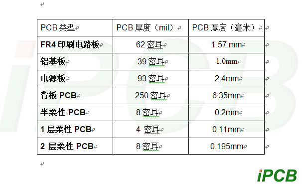
Boards with thicknesses ranging from 15.7mil (0.4mm) to 39.4mil (1.0mm) are known as thin PCBs. These boards are lightweight and flexible, making them suitable for applications where space and weight are critical. These PCBs are often used in portable electronics, wearables, and devices that require flexibility. - Thicker PCBs
Boards with thicknesses ranging from 62mils (1.6mm) to 93mils (2.4mm) and above are known as thick PCBs. These boards have greater mechanical strength and durability than thin PCBs, making them suitable for applications where ruggedness is critical. Thicker boards are often used in industrial applications, power electronics, and consumer electronics where the boards need to withstand mechanical stress. - Extremely Thick PCBs
Some printed circuit boards can be thicker than 93mils (2.4mm), and backplane PCBs can be as thick as 400mils (10.16mm). These PCBs are often backplanes or test boards that contact thousands of extremely large components.
Standard PCB Thickness
After understanding the main factors of circuit board thickness, let’s talk about standard PCB thickness or typical PCB thickness. Generally speaking, the most commonly used PCB thickness is 62mils (1.57mm), but the thickness will vary slightly depending on the PCB material and PCB type.
The Impact of thick pcb board on the Performance of Electronic Equipment
Electrical Performance: The thickness of the PCB determines the cross-sectional area of its conductive layer, which affects the current transmission capacity. Thicker PCBs have a larger conductive cross-sectional area, can withstand higher currents, reduce line impedance, and reduce signal transmission losses.
Thermal Performance: PCBs carry electronic components in electronic devices, and their thickness directly affects the heat dissipation effect. Thicker PCBs have greater heat capacity and better thermal conductivity, which can more effectively conduct the heat generated by electronic components and improve the thermal stability and reliability of electronic equipment.
Mechanical Performance: The thickness of the PCB is also closely related to its mechanical strength and stiffness. Thicker PCBs have higher bending stiffness and impact toughness, can withstand greater mechanical stress and vibration, and ensure the stability and reliability of electronic equipment in harsh environments.
Thick pcb board also have a certain impact on costs
Material cost: The material costs used for PCBs of different thicknesses are different. Generally speaking, thicker PCBs require more raw materials, so the material cost is relatively high. Processing cost: Thicker PCBs require higher precision and greater force during processing, which will increase the investment and maintenance costs of production equipment, thereby increasing processing costs.
Thick pcb board have an important impact on the performance, production process, and cost of electronic equipment. When choosing the thickness of the PCB, it is necessary to comprehensively consider factors such as the performance requirements of electronic equipment, production process conditions, and cost control to ensure that the design and manufacturing quality of the PCB meet the requirements of electronic equipment.
