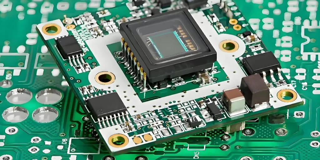
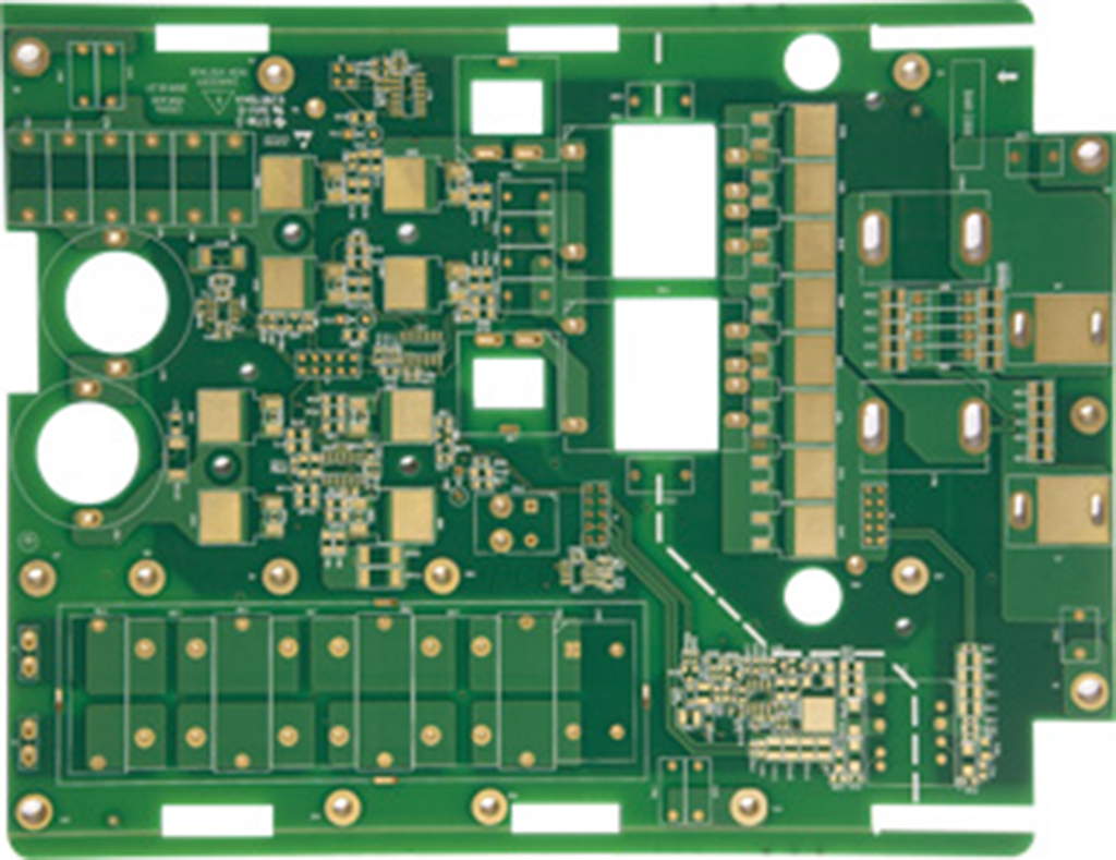
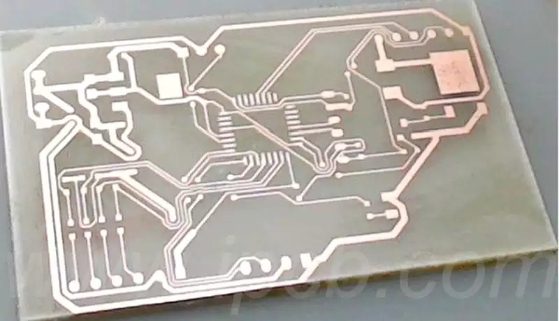
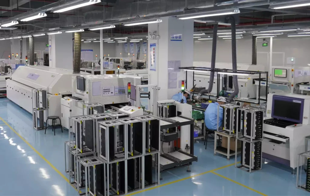
Printed circuit board repair, as an important part of the maintenance of electronic equipment, is vital to ensure the proper functioning of the equipment. It is important to understand the basic components of a circuit board. Circuit boards are usually made up of wires, electronic components and solder joints. The wires are used to carry current, the electronics form the core of the circuit, and the solder joints are used to connect the wires to the electronics. Knowing the structure of a circuit board is very helpful in locating and solving problems.
Before performing printed circuit board repair,it is important to have a basic knowledge of electronics. Familiarity with common electronic components such as resistors, capacitors, diodes and transistors is essential in determining the cause of a malfunction. Understanding their nature, characteristics and usage can quickly pinpoint the problem and improve printed circuit board repair efficiency.
The first step in treating a circuit board that needs to be repaired is to carry out an intuitive visual inspection, with the aid of a magnifying glass if necessary, to obtain a more detailed observation.
In the inspection process, we need to pay attention to the following points:
Whether the connection lines on the circuit board are broken or sticking, especially whether the printed circuit board connection lines remain intact;
Whether the relevant components, such as resistors, capacitors, inductors, diodes, transistors, etc., are broken;
Whether the circuit board has been repaired by others traces of the specific components moved, and whether there is a false soldering, leakage of welding, insertion of reverse insertion and other issues.
In the test, we follow the ‘first outside and then inside’ principle, that is, first from the circuit board’s external ports to start testing, and gradually deep into the internal. The use of circuit online maintenance tester, it is best to have a good circuit board as a comparison, the use of the tester’s dual-rod VI curve scanning function of the two circuit boards for comparative testing, especially the comparison of capacitor testing to make up for the multimeter online test is difficult to find the defects of capacitor leakage.
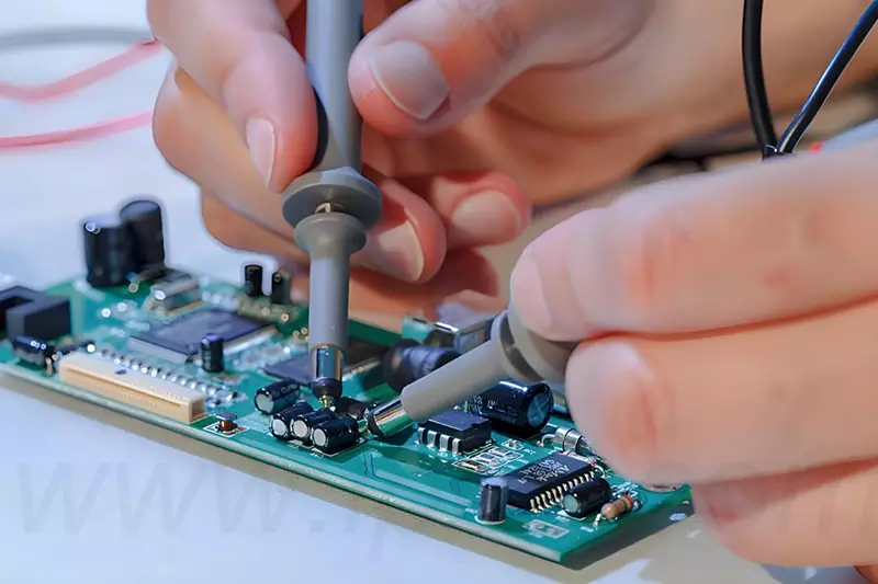
In the testing process, we adopt the strategy of ‘easy before difficult’. In order to obtain more accurate test results, we need to perform a series of technical treatments on the printed circuit board repairs before testing to eliminate potential interference. These include:
Preparation before testing:gently touch the two ends of the crystal to short circuit,for large-capacity electrolytic capacitors, then solder down one of its feet, so that it is no longer involved in the circuit work, in order to reduce the interference signal;
Using the exclusion method to test the device: for the test passed (or more normal) device,directly confirm the test results and record. For devices that fail the test (or are relatively ultra poor),retesting can be carried out. If it still does not pass,also confirm the test results, and then continue to test other devices.After all devices have been tested,then deal with those devices that do not pass the test;
Comparative testing of devices not yet covered by the test library using ASA-VI curve scanning technology:with its excellent adaptability, this technology can easily cope with comparative testing of all types of devices.Through sophisticated comparison tests,ASA-VI not only demonstrates strong fault detection capabilities,but also excels in determining device status.
Finally,we followed the principle of ‘first static, then dynamic’ for real-world testing. Although we have conducted in-line functional testing and static characterisation of the components on the board, this can only be used as a preliminary judgement. In order to ensure that the circuit board has been fully repaired, we need to re-install it into the original equipment to carry out the actual operation of the test. During this process, we need to ensure that the power supply to the device is accurately supplied to the board, and that every interface plug-in on the board must be tightly connected. At the same time, we also need to exclude the circuit board environment and peripheral circuitry may bring adverse effects to ensure that the printed circuit board repair work is correct.
Printed circuit board repair needs to be combined with professional knowledge, advanced tools and practical experience to ensure that the repair is accurate and efficient, to ensure the stable operation of the equipment. I hope this article can provide you with valuable guidance.
