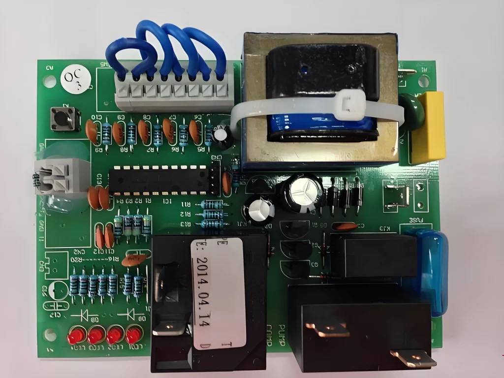
Circuit boards are known by the following names: circuit board, PCB board, aluminum substrate, high frequency board, thick copper board, impedance board, PCB, ultra-thin circuit board, ultra-thin circuit board, printed (copper etching technology) circuit board, etc. Circuit boards make circuits miniaturized and intuitive, and play an important role in the mass production of fixed circuits and the optimization of electrical appliance layout. PCBs are the backbone of modern technology. Mobile phones, airplanes, and many other things contain semiconductors, and they make many of our lives possible.But they can fail, and when they do, it can be expensive to replace them. Improper handling, overheating, or other accidents can damage PCBs. When this happens, you may need to repair your PCB. This article shares useful tips for PCB repair. Today we will introduce you to circuit board repair near me, simple circuit board repair tips, production processes, etc.
So what are some of the reasons for the failure of printed circuit boards?
- Physical damage
There are many different reasons for the failure of printed circuit boards. Physical damage is one of them. Such damage can occur when the circuit board is dropped or even improperly handled during transportation. The most common physical damage occurs when the traces on the circuit board are disconnected. This can be caused by static electricity, electrostatic discharge, or other sources of electrical energy. - Component Failure
This is one of the reasons why printed circuit boards fail. It happens when one or more of the components on a PCB don’t function as expected. Circuit boards are assembled by soldering components together, and solder joints can fail for a number of reasons. Most commonly, a component will fail because it wasn’t properly soldered in the first place. - Gold Finger Damage
Gold fingers are the tiny, delicate components that connect the traces on a circuit board to the pads. They’re designed to be small enough to fit in tight spaces and make connections without much effort, but when you’re working on a PCB, sometimes you need to get into those tight spaces with tweezers or tweezers to make sure everything is connected correctly. The more you do this, the more likely you are to accidentally bend or break one of the gold fingers, which means your board won’t work at all. - BGA Pad Damage
These are the small spots on a circuit board where soldered components are connected. BGA pads can become damaged if they’re exposed to high temperatures for too long, or if they’re not properly insulated from a heat source, like a soldering iron or hot chip. This can also cause cracks or other deformities that make it harder for current to flow through them. - Damaged Through Holes and Vias
Through holes and vias are the small holes you see on your PCB. When these holes get damaged or broken, it can cause serious problems with your board. The reason for failure here is that when you solder components to the board, if one of these holes gets damaged or broken, it can cause a short circuit. This will cause your entire board to fail because it will no longer function properly. - Corrosion
As the name suggests, corrosion is a process where one material eats away at or breaks down another. Most materials corrode when they come in contact with corrosive elements like water or oxygen.
In some cases, corrosion can occur on a printed circuit board due to humidity or condensation accumulating on the printed circuit board. This can happen if the board is exposed to heat for a long time or if there is a lot of humidity in the surrounding environment. - Broken Traces
Printed circuit boards consist of thin copper layers that conduct electricity. PCB traces connect different parts of the board and carry signals. When a trace is broken, it does not conduct electricity. Impact or excessive heat can cause a trace to break. This can cause the board to fail. Broken traces may not be visible to the naked eye. - Damaged Edges
The edges of a circuit board are not only the most vulnerable part of a PCB, but they are also one of the most important. That’s because the edges are where all the connections meet and connect – so if you damage them in any way, you can cause a lot of problems. Damaged edges of circuit boards can lead to short circuits and electrical failures, which can cause fires and other safety issues. - Solder Mask Delamination
One of the most common problems with printed circuit boards is solder mask delamination, which occurs when the solder mask separates from the copper layer beneath it due to improper adhesion or other physical damage. When this happens, it leaves an unprotected area on the board where electronic components can short to each other or to the ground plane or other conductive paths on the surface of the board. If this situation is allowed to persist and go unchecked, permanent damage can occur to individual components and the entire system due to multiple components overheating or shorting at the same time.

Circuit Board Repair Tips: Observation Method
This method is fairly intuitive, and the burn marks can be clearly seen through careful inspection. When using this method, you need to pay attention to the following issues:
Step 1: Determine whether the circuit board is damaged by human intervention by observing the following aspects:
(1) Whether the board corners are deformed; whether the chip is deformed; whether other components are deformed.
(2) Whether there are traces of prying on the chip or socket.
(3) Whether the circuit board chip is plugged in properly, which will damage the circuit board when powered on, so pay attention.
(4) Whether the corresponding short-circuit terminals of the circuit board are plugged in incorrectly or reversely.
Step 2: Carefully observe the components related to the circuit board, and observe each capacitor, resistor, etc. to see if there is any blackening. Since the resistor cannot be seen, it can only be measured with an instrument. Related bad parts should be replaced in time.
Step 3: Observe the integrated circuits of the circuit board, such as CPU, AD and other related chips. If bulging, burning, etc. are observed, they should be modified in time.
The cause of the above problems may be in the current. Excessive current causes burning, so check the relevant circuit diagram to see where the problem is.
Circuit board maintenance skills: static measurement method
In maintenance, it is often difficult to find some problems by observation, unless it is obviously burned or deformed. However, most problems still require the measurement of the voltmeter to draw conclusions, so the components and related parts of the circuit board must be tested one by one. The main tool is the multimeter, and the process is as follows:
Step 1: Detect the short circuit between the power supply and the ground to see the cause.
Step 2: Check whether the diode is normal.
Step 3: Check whether the capacitor is short-circuited or even open-circuited.
Step 4: Check the indicators of related integrated circuits and resistors related to the circuit board.
The observation method and static measurement method can solve most of the problems in circuit board maintenance, but when measuring, make sure that the power supply is normal and no secondary damage occurs.
Circuit board maintenance skills: online measurement method
The online measurement method is generally used in manufacturers that mass produce circuit boards. In order to facilitate maintenance, manufacturers generally build a more general debugging and maintenance platform, which can easily provide the power supply required by the circuit board and some necessary initial signals. The online measurement method mainly solves two problems: one is to subdivide the problems found in the above two steps and finally lock the components with problems; the other is that if the problems are not solved through the above two steps, the cause of the failure needs to be found through online measurement. In addition, you can also find a circuit board repair near me. The online measurement method is mainly carried out through the following steps:
Step 1: Power on the circuit board. In this step, it should be noted that some circuit boards do not have a single power supply and may require 5V, 12V, 24V, etc. After the circuit board is powered on, touch the components on the circuit board to see if there are any hot components. Focus on checking the 74 series chips. If the components are hot, it means that the components may be damaged. After replacing the components, check whether the circuit board failure has been solved.
Step 2: Use an oscilloscope to measure the gate circuit on the circuit board to observe whether it conforms to the logical relationship. If the output does not conform to logic, it needs to be treated separately in two situations. One is that the output should be low level, but the actual measurement is high level, which can directly determine that the chip is damaged; the other is that the output should be high level, but the actual measurement is low, which cannot determine that the chip is damaged. The chip needs to be disconnected from the subsequent circuit and measured again to observe whether the logic is reasonable and determine whether the chip is good or bad.
Step 3: Use an oscilloscope to measure the crystal oscillator in the digital circuit to see if it has output. If there is no output, it is necessary to remove as many chips connected to the crystal oscillator as possible before measuring. If there is still no output, it is preliminarily determined that the crystal oscillator is damaged; if there is output, it is necessary to install the removed chips one by one, install one and test one, and find out where the fault is.
Step 4: Digital circuits with bus structures generally include three buses: digital, address, and control. Use an oscilloscope to measure the three buses, compare the schematic diagram, observe whether the signal is normal, and find out the problem.
The online measurement method is mainly used to compare two good and bad circuit boards. Through comparison, problems can be found and solved. Thus, the circuit board repair is completed.
Why do you need to know how to repair PCBs?
The answer is simple, because PCBs are the brains of every electrical device, and you must know how to repair them. If you want to repair your gadgets, or even just want to understand what’s going on in them, you must learn how to repair PCBs. Unless you have a “circuit board repair near me” in your mind, as a professional engineer, sometimes some small problems can be solved by yourself.
When a PCB fails, it can cause all kinds of problems in your electronic devices. If your computer motherboard or processor is damaged due to a damaged PCB, you will no longer be able to use it until it is repaired. These circuits are important to know how to repair because they make our lives possible in many aspects.
The above circuit board repair methods can still help friends solve emergency problems in most cases. Of course, it is not ruled out that it is really impossible, then it will be recommended that everyone find a circuit board repair near you. With the advancement of technology, the price of some electronic devices has risen, and it is very important to protect the circuit board.


