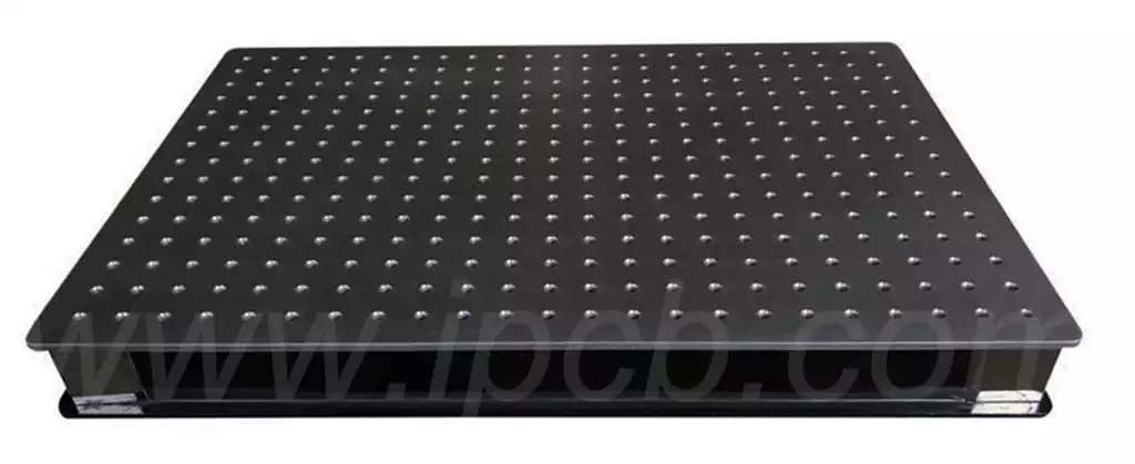
Mini Breadboard that is, ‘integrated circuit experiment board’, is a plug-in board, this ‘board’ has a number of small ‘socket (hole)’. When conducting circuit experiments, you can insert the pins and wires of electronic components into the corresponding holes according to the circuit connection requirements, so that they contact with the flexible contact reeds in the holes, thus connecting the required experimental circuits.
The breadboard’s ingenious design, which is full of small jacks, provides a convenient way to access electronic components. Engineers can easily insert the components into the appropriate jacks according to the actual needs, thus saving time on soldering and increasing the reuse of components.
The bottom of the mini breadboard is cleverly designed with metal strips. By drilling holes at specific locations on the board, components can be inserted in close contact with the metal strips, thus realising the conductive function. Each side of the mini breadboard is equipped with 4 sets of 8 horizontally connected jacks, which are designed for the introduction of power, and we call them power holes. The middle section, on the other hand, is divided into an upper and lower part, where every 5 holes form a longitudinal channel (these holes are connected), which constitutes our main working area and is mainly used for plugging in components and jumpers. The design of the centre notch not only clarifies the disconnection boundary between the upper and lower sections, but also ensures that the holes immediately adjacent to the notch are spaced 7.62mm apart, which is just right for standard narrow-body, dual in-line direct insertion (DIP) pin integrated circuits (ICs).
Steps for using the mini breadboard:
Prepare all kinds of electronic components, such as resistors, capacitors, light-emitting diodes (LEDs), etc., and prepare the necessary wires for connection and auxiliary materials such as power supply.
Insert the pins of the electronic components into the corresponding holes of the mini breadboard, and make use of the conductive properties of the metal pins inside the mini breadboard to realise the electrical interconnection between the components.
The power supply end of the mini breadboard is reliably connected to the external power supply system through wires, so that the whole circuit can obtain the power required for normal operation.
According to the actual design requirements, the circuit architecture can be dynamically adjusted or new components can be added at any time. The circuit can be reconfigured by simply plugging and unplugging the components or adjusting the position of the wire connections during the adjustment process.
Operating instructions for jumper cables
Jumper wires, which are used to connect non-adjacent parts of a circuit, play an important role in electronic circuit experiments and electronic crafts. By using jumpers, we can efficiently construct complex circuit layouts while minimising the occurrence of misconnections and soldering errors.
The following are the steps for using jumper wires:
- Identify and locate the two circuit parts that need to be interconnected and their corresponding pin positions.
- Use jumper cables to connect, the specific approach is to jumper cable ends were firmly inserted into the two parts of the pins of the socket.
- The solidity of the jumper connection should be verified and the circuit should be checked for smooth operation.
- According to the actual demand, you can flexibly adjust the jumper connection configuration or add new jumper connections.
Mini breadboard is suitable for a variety of circuit experiments, prototyping and debugging, and can be used for students‘ electronic experiments, hobbyists’ DIY production, engineers’ prototyping and so on. Using the breadboard can greatly improve the efficiency and accuracy of circuit building and testing.