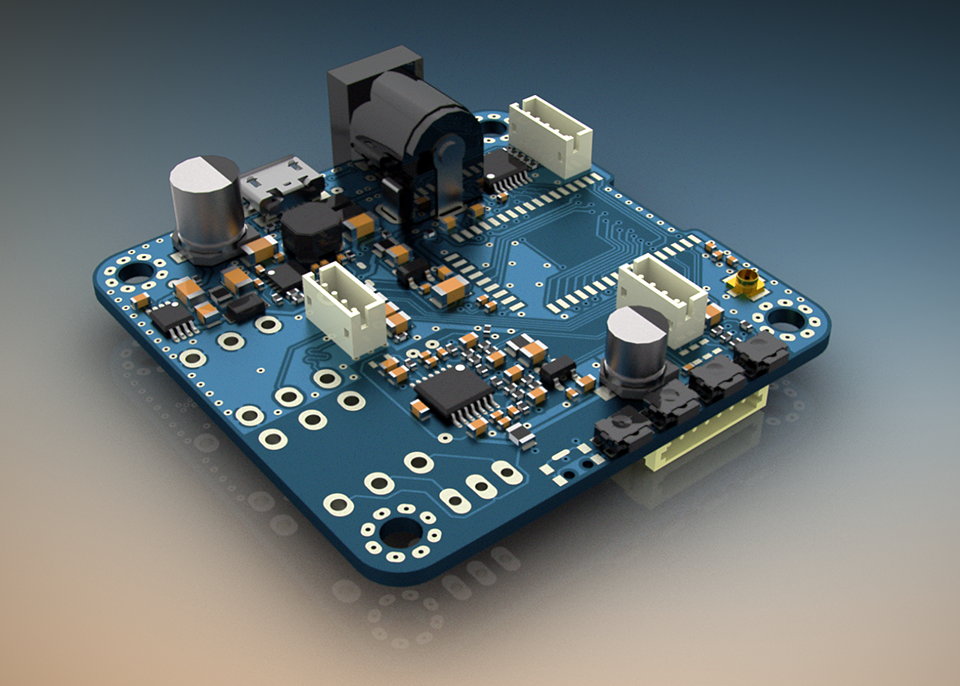
A potentiometer circuit board is an analogue circuit element used in electronic circuits, usually to adjust the resistance of a circuit in order to control its performance and function. It usually consists of a rotary potentiometer, a potentiometer resistor, two connecting wires and two connectors.
Potentiometer circuit board is mainly composed of a rotary potentiometer, a resistor body, wires and connectors. The potentiometer resistor body is the main part of the circuit board potentiometer and is usually made of a piece of adjustable resistance material. The rotary potentiometer is used to control the position of the potentiometer resistor body to adjust the circuit resistance.
Potentiometer circuit board has the following features and advantages and disadvantages:
- Highly adjustable. Circuit board potentiometers can achieve stepless adjustment of resistance value by rotating the potentiometer, which is very flexible.
- good stability. Circuit board potentiometer resistance value change range is small, the adjustment process will not appear large voltage or current fluctuations, stability is good.
- easy to use. Circuit board potentiometer small size, light weight, easy to install and use.
- short life. Circuit board potentiometer life is relatively short, easy to wear and tear due to frequent use, or even failure.
The role of the potentiometer circuit board
Regulate circuit resistance
As a key device for regulating circuit resistance, the core function of the potentiometer is to flexibly adjust the resistance value in the circuit to achieve precise control of the current and voltage in the circuit. Potentiometers are indispensable in scenarios where circuit resistance needs to be changed, such as volume adjustment and brightness adjustment.
Circuit voltage divider
Potentiometers are also capable of dividing the voltage in a circuit. When there are multiple loads with the same topology in the circuit, and these loads require different operating voltages, we can adjust the resistance of the potentiometer to change the output voltage of the circuit, so as to achieve the purpose of voltage dividing and control of different loads. Potentiometers are commonly used in scenarios that require precise voltage control, such as reference voltage setting in ADC circuits and zero bias voltage adjustment in comparators.
Adjusting Amplifier Circuit Gain
Potentiometers can also be used to adjust the gain of an amplifier circuit. By adjusting the resistance value of the potentiometer, the feedback circuit structure of the amplifier can be changed, and the size of the feedback resistor can be adjusted accordingly, thus affecting the voltage gain of the amplifier. Potentiometers are also essential components in scenarios where signal gain needs to be adjusted, such as Q setting in filter circuits and amplifier magnification adjustment.
Potentiometer circuit board operates based on a change in resistance. As the contact moves across the resistor body, it changes the length of the resistance connected to the circuit, thus changing the resistance value. This mechanism enables the potentiometer circuit board to precisely adjust the circuit parameters according to the actual demand, and realise the fine-tuning or control function of the circuit.
Potentiometer circuit board has a wide range of applications in electronic equipment, such as volume control in audio equipment, power supply circuit voltage regulation. In addition, in industrial automation, automotive electronics, aerospace and other fields, potentiometer circuit boards also play an important role in providing key support for the stable operation of equipment.