In the PCBA mass production process, due to the expansion of production scale and process complexity increases, often encounter some common problems. The following will explore these issues in depth and provide the corresponding solutions.
Design and Material Preparation Stage
Ignoring the special needs of mass production during the design phase can lead to subsequent manufacturing difficulties. Many designers follow the high-volume thinking for component selection and BOM configuration, ignoring the logic of low-volume procurement, resulting in a significant increase in the procurement cost of cold packages and very small-size components. Therefore, an accurate BOM list should be prepared in advance, and priority should be given to the selection of general-purpose packages and components with stable stock supply.
Soldering Defects
Soldering defects are one of the most frequently occurring problems in PCBA manufacturing, manifesting themselves in false soldering, cold soldering, short circuits and open circuits.
False soldering refers to a weak connection of the solder joints, usually due to incomplete melting of the solder or insufficient amount of solder. To address this problem, the temperature and time of soldering should be accurately controlled, the appropriate solder should be selected, and the reflow soldering equipment should be calibrated and inspected regularly to ensure that the temperature profile meets the process requirements.
Cold soldering refers to the solder joints, although the appearance of normal, but did not reach a sufficient soldering temperature, resulting in an unstable electrical connection. The solution is to adjust the heating parameters of reflow soldering to ensure that the soldering temperature reaches the standard requirements, and at the same time, regular maintenance and temperature calibration of the equipment.
Short-circuit and open-circuit problems, short-circuit mostly due to too small a pitch, welding direction is incorrect or welding speed is too fast; open-circuit is the circuit board line breakage caused by electrical interruptions. In this regard, the PCB design layout should be optimised to avoid overly dense lines, and the use of automatic optical inspection (AOI) and X-ray inspection and other technical means to detect and correct short-circuit and open-circuit defects in a timely manner.
Component Position Errors
Component position error occurs during the surface mount (SMT) process and can cause circuit malfunction or even short circuits.
Offsets are deviations in component position during placement, usually caused by inaccurate calibration of the placement machine or uneven distribution of solder paste. Solutions include ensuring regular machine calibration and maintenance, and optimising the solder paste printing process to ensure uniform application.
Warping phenomenon is due to the uneven size of the pads on both sides of the generation of unbalanced tension, or preheating temperature rise too fast, mechanical placement deviation caused by component tilt. This can be improved by adjusting the rate of preheating temperature rise, improving placement accuracy, and adjusting the thickness of solder paste printing.
Solder paste printing problems
The quality of solder paste printing directly affects the soldering effect, common problems are uneven thickness of solder paste and poor adhesion of solder paste.
Uneven distribution of solder paste thickness can lead to soldering defects such as cold soldering or false soldering. In this regard, the solder paste printing equipment should be regularly maintained to ensure that the printing pressure and speed to meet the process requirements, the use of high-quality solder paste, and regularly test the uniformity of the solder paste and the degree of adhesion.
Poor paste adhesion affects the fluidity of the paste, which in turn affects the quality of the solder. Solutions include ensuring that the solder paste is stored and used in a suitable environment, preventing the paste from drying out or deteriorating, and regularly cleaning the printing template and squeegee to keep the equipment in good working condition.
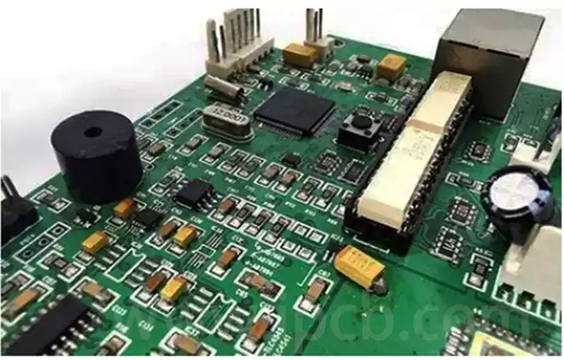
Printed circuit board (PCB) defects will also have an impact on the quality of PCBA, common problems include open and short circuit.
An open circuit refers to a broken PCB line, resulting in an interruption of the electrical connection. To prevent such problems, the PCB design stage should be strictly implemented in the design rules check to ensure that the line layout in line with the manufacturing specifications; in the production process, the use of automatic optical inspection (AOI) and other advanced detection means, timely detection and repair of line breaks.
A short circuit is an undesirable electrical connection between two or more lines on the PCB. Solutions include optimising line design to avoid overly dense lines, and using X-ray inspection technology in the manufacturing process to check for possible short circuits within the PCB to ensure that the electrical performance meets the design requirements.
Material Procurement and Supply Chain Management
The instability of the supply chain and the varying quality of materials can also lead to production problems. Components and PCB boards should be purchased from reputable suppliers and subjected to strict warehousing inspection to avoid mixing defective products into the production line. Long-term stable supply chain relationship and supplier evaluation system can help prevent production interruption and rework caused by material problems.
Difficulties in quality control during production
In mass production, how to ensure the quality control of each link becomes difficult. Strict implementation of Design Rule Check (DRC) and process flow, and the establishment of quality inspection links such as first piece inspection, self-inspection, and special inspection help to detect problems in time. In addition, maintaining and calibrating key equipment, standardising operating procedures and strengthening staff training are key measures to ensure consistency and stability.
Quality Control and Continuous Improvement
In order to ensure the quality of PCBA mass production, strict quality control and continuous improvement strategies must be implemented.
Quality Inspection: Conduct comprehensive quality inspections during the production process, including functional testing, electrical testing, etc., to ensure that the quality of each batch of products meets the standards.
Quality Improvement: Using production data analysis and feedback, we continuously optimise the production process, material selection and technical parameters to enhance production efficiency and product quality.
Employee Training: Train employees to ensure they are familiar with standardised operating procedures and quality standards to improve production consistency and quality.
Failure analysis and continuous improvement
Timely failure analysis is the basis for quality improvement in the PCBA production process. Common failure modes include circuit board rubbing, abnormal copper surface dry film adhesion, uneven tin layer, and poor plating melting tin. Failures can be effectively prevented by standardising the manufacturing process, reducing physical friction, selecting high-quality materials and strictly controlling the plating process. Establish a perfect quality traceability system and improvement mechanism to achieve continuous optimisation and ensure product reliability and stability.
Through the implementation of effective solutions to improve the overall quality of PCBA processing, reduce production costs and improve production efficiency. This is of great significance for enterprises to gain advantages in the fierce market competition.
