A breakout board, called both an adapter board and a breakout board, is a board-like device used to connect, convert, or extend the functionality of electronic equipment. It can establish a connection between different devices or components to achieve signal transmission, conversion or processing. Adapter boards are widely used in a variety of electronic equipment, such as computers, communication equipment, audio and video equipment, etc., to improve the compatibility, flexibility and expandability of the equipment.
The structure of breakout board usually consists of the following core parts:
Substrate Material
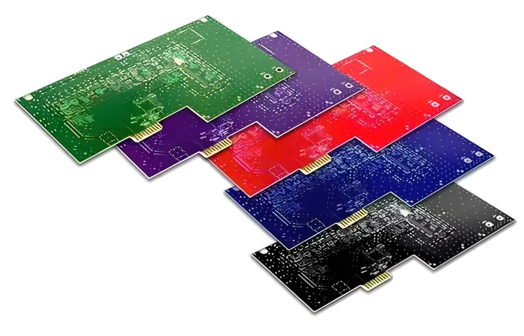
Substrate material is the foundation of breakout boards, and its selection directly affects the performance of adapter boards. Commonly used substrate materials include FR-4 glass fibre, as well as special materials for high-frequency applications, such as Rogers RO4350B. FR-4 is a common flame-retardant grade designation, which stands for the specification of a resin material that is self-extinguishing in a burning state, and it is usually made from a composite of a four-functional epoxy resin, a filler, and glass fibre, which is high-temperature-resistant, insulating, and flame-retardant. Characteristics. High-frequency materials are suitable for high-frequency circuits, where the dielectric constant (DK) and dielectric loss factor (DF) vary less at different frequencies and are critical for signal transmission. Substrate thicknesses typically range from 0.2 mm to 3.2 mm, with specific choices adapted to the needs of the application. For example, 0.7 mm and 1.5 mm thick PCBs are commonly used for double-sided board designs with gold fingers, while 1.8 mm and 3.0 mm are non-standard sizes.
Connection Interfaces
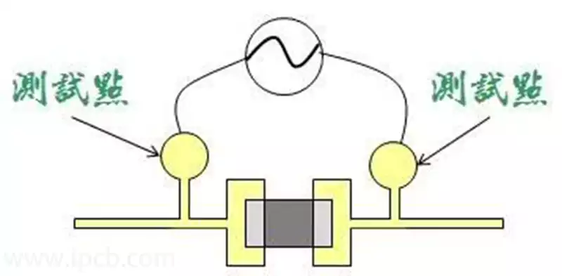
Connection interfaces are key to physically and electrically connecting the breakout board to the target device. These interfaces can include 2.54 mm pitch pins, gold fingers (e.g., PCIe interface), and solder pads to ensure compatibility between the adapter board and various devices.
Circuit Layer Design
The circuit layer design of an breakout board may incorporate a variety of features to address signal compatibility issues. These include impedance matching circuits to optimise signal transmission, signal amplifiers to boost signal strength, and level shifters (such as the TXB0108) to convert signals between devices with different voltage levels. For example, in industrial automation, an adapter board can convert RS-232 signals to RS-485 signals when there is a mismatch between the programmable logic controller (PLC) and the sensor interface. This conversion can extend the signal transmission distance from 15 metres in RS-232 standard to 1200 metres in RS-485 standard, which greatly improves the reliability and coverage of communication.
Types and functions of a breakout board
- Breakout boards: These boards are mainly used to connect devices with different interface types, such as connecting a USB device to a computer with different types of interfaces. Breakout board can convert signal formats, voltage levels, or data transfer rates to ensure proper communication between devices.
- Expansion breakout boards: Expansion adapter boards are used to increase the number of functional interfaces on a device, such as expanding a single USB port on a computer motherboard into multiple USB ports. In this way, users can connect more devices at the same time to improve the efficiency of the use of equipment.
- Special function breakout board: this type of adapter board has a specific function, such as for network equipment in the fibre optic adapter board, audio and video equipment in the signal converter and so on. These adapter boards can meet the needs of specific application scenarios and improve the overall performance of the equipment.
Advantages of Adapter Boards
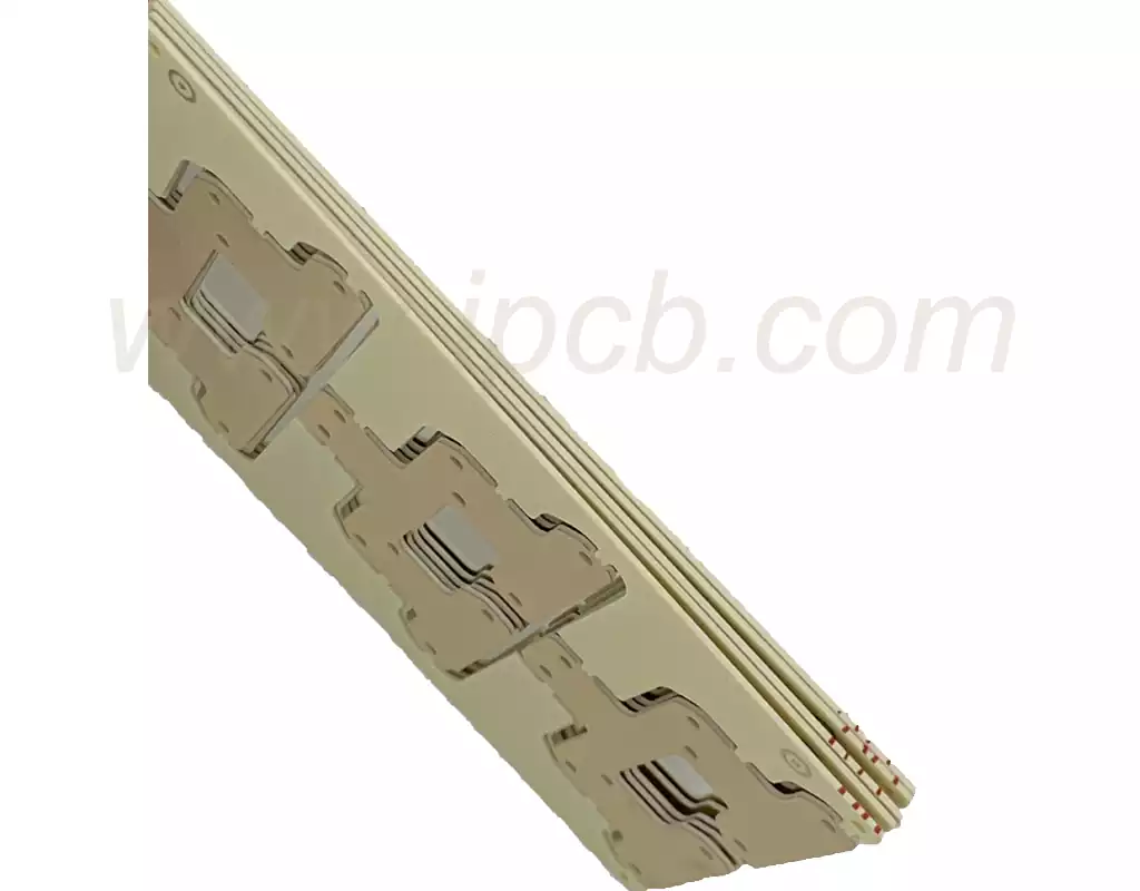
High-density I/O interconnect. As interconnect densities and the number of I/Os increase dramatically, the pitch of metal bumps for flip-flop soldering is required to be reduced, resulting in metal bumps that are challenging to produce in terms of both cost and manufacturing difficulty.Adapter boards utilise RDL layers with small line widths and high-density wiring to enable redistribution of high-density I/O, thereby reducing the requirement for small-pitch bumps. TSV-based adapter boards can redistribute high-density I/O on the backside of the adapter board while shortening the length of the chip-to-board interconnect, reducing power consumption and latency.
Improved integration. Smaller RDL line widths and higher wiring densities on the adapter board can improve system integration. Although the system area increases and the integration level is relatively small compared to 3D integration, the adapter board can increase the integration level and reduce the system area to a certain extent compared to the lead bonding method.
Heterogeneous integration. The breakout board can encapsulate different functions, different processes and different substrates of the chip, to achieve the heterogeneous integration of the system, increasing the functionality of the system.
The core role of the breakout board
- Interface conversion
Solve the protocol differences between old and new devices, such as converting HDMI interface to DP interface to support 4K@60Hz video transmission (the bandwidth needs to reach 17.28Gbps).
In embedded development, convert the 40-pin GPIO port of Raspberry Pi to a standard JTAG interface for easy debugging. - Size Adaptation
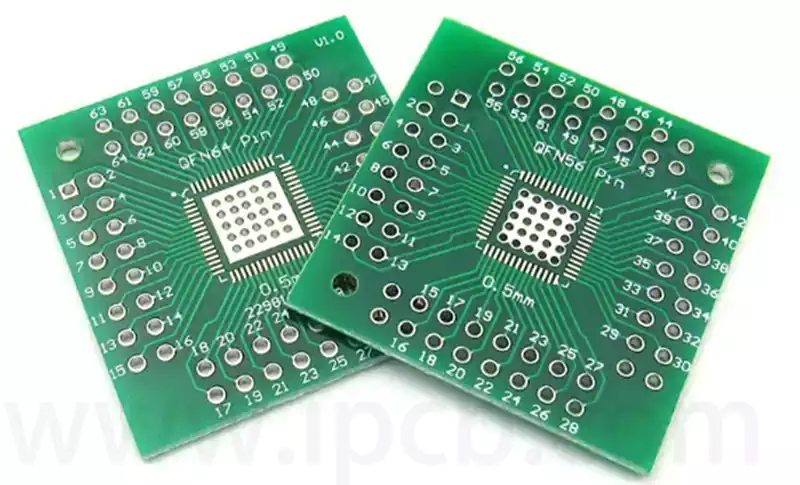
Miniaturisation: Adapt BGA package chips (e.g. 0.4mm ball pitch) to QFP package for easy manual soldering.
Expanded space: High-density connectors (e.g. M.2 Key M) are led out to a larger area PCB through an adapter board. - Function Expansion
Increase peripheral support: such as expanding multiple serial ports through USB breakout board (CH340G chip programme, supports 16C550 UART protocol).
Power supply adaptation: convert 5V input to 3.3V/1.8V multiple outputs (using TPS5430 buck chip, efficiency up to 95%).
As an important part of electronic design, the breakout board effectively solves the challenges of inter-device compatibility, size adaptation and function expansion through its diverse substrate materials, flexible connection interfaces and sophisticated circuit layer design. It not only improves the integration and flexibility of electronic systems, but also plays an indispensable role in interface conversion, signal optimisation and heterogeneous integration, and is the key to the efficient interconnection and functional diversity of modern electronic devices.