A current divider, also known as a current shunt, is a component used to distribute current to support multiple circuits. It divider current from one circuit to multiple branch circuits, each of which can have a different resistance value as needed.
Current divider key characteristics:
- Extremely low resistance: common range 0.01mΩ~100mΩ, need to use materials with low temperature coefficient (e.g. manganese-copper alloy, α≤5ppm/°C).
- High precision: industrial grade shunt error ± 0.5%, laboratory grade up to ± 0.1% (refer to IEC 62053-21 standard).
- High power tolerance: heat dissipation needs to be calculated, e.g. 500A/50mV shunts consume up to 25W (P=I²R) and need to be equipped with heat sinks.
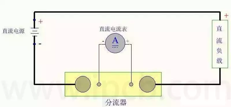
Current divider is based on the principle of DC current flow through the resistor when the voltage generated at both ends of the resistor made, the shunt is actually a very small resistance, when there is a DC current flow through, resulting in a voltage drop for the DC ammeter display, DC ammeter is actually a voltmeter, the general range of this voltmeter 75mV, 150mV, 300mV, with a voltmeter to measure this voltage, and then the voltage converted to current, it is completed. The voltage is converted to current, and the measurement of high current is completed.
In low frequency small amplitude current measurement, it shows high accuracy and fast response speed. In the industrial field, the divider is the preferred low cost solution for converting current signals into voltage signals in applications that do not involve galvanic isolation between the measuring circuit and the measured current.
Current divider application method
- Selection of current divider method
(1) According to the use of ammeter (or current-voltage dual-purpose meter) marked on the dial of the number of mV to choose the rated voltage drop current specifications (generally used is 75mV or 45mV). If the ammeter does not have this value, then use the following formula to calculate the voltage limit of the table, and then select the rated voltage drop specifications of the shunt.
Table voltage limit (mV) = ammeter full scale current (A) x ammeter resistance (Ω) x 1000
(2) Select the rated current specification of the divider according to the current range to be expanded
(3) The selected shunt two current terminals were connected to the power supply and load, the potential end of the ammeter, should pay attention to the polarity of the ammeter terminals to be connected to the right, the ammeter’s range will be expanded to the divider on the calibration of the current value.
2.Calculation method of ammeter multiplier after using divider
For motor test measurement, often an ammeter should be configured with more than one shunt to solve the problem of ensuring the required measurement accuracy in a larger measurement range. At this time, the requirements of all shunts used in the rated voltage drop with the ammeter with the same, for example, 75mV. so, after the selection of shunts, the full scale of the ammeter is the rated current value of the selected shunt, the ammeter multiplier (i.e., the number of currents per frame of the dial scale) that is, for the shunt’s rated current divided by the total number of frames on the dial scale.
Shunts for DC current measurements are available in slotted and non-slotted versions. The current divider has a manganese-nickel-copper alloy resistor bar and copper strip with a nickel coating. Their voltage drop is rated at 60 mV, but they can also be used as 75, 100, 120, 150 and 300 mV.
Main functions of current divider:
- Measurement of large DC currents
In the power industry it is often necessary to measure high currents, and direct measurement of high currents may cause damage to the measuring equipment. The current shunt, through its special construction, is able to generate a small voltage drop when high currents pass through it, which is proportional to the current through the shunt. Therefore, we only need to measure this small voltage drop to accurately deduce the value of the high current through the shunt. This method is both safe and accurate, and is widely used in the power industry for high current measurement. - Protection Circuit System
In addition to the measurement function, the electric current divider also serves the important duty of protecting the circuit. In circuits, excessive currents may damage equipment or cause circuit failures. An electrical shunt can shunt the excessive current, i.e., direct a portion of the current to ground or other branch circuits by means of an electrical shunt, thus reducing the current intensity in the main circuit and protecting the circuit and equipment from damage caused by excessive current.
Core Application Scenarios of current divider
- New Energy Field
Electric Vehicle: Used in Battery Management System (BMS) to monitor the charging and discharging currents, the typical divider rated current is up to 300A~1000A, and the accuracy needs to meet within ±0.5% (refer to ISO 16750-2).
Photovoltaic power generation: detect DC side current in inverter, common specification is 150A/75mV, withstand voltage level above 1kV.
- Industrial automation
Scenarios such as inverter and motor control require real-time current monitoring, and shunts are less costly and do not require external power supply compared to Hall sensors. For example, a model of 5kW motor control using 20mΩ shunt, measurement error <1%. - Power system protection
Overcurrent protection with relays, e.g. 500A/100mV shunt in a 10kV distribution cabinet, with a response time of <10ms (according to IEC 60255).
As a key electronic component, current divider plays an irreplaceable role in current measurement, circuit protection and multi-disciplinary applications. As technology continues to develop, current divider will continue to play a key role in various fields, providing reliable support for the development of power systems, industrial control and new energy technologies. Its unique advantages make it the component of choice for engineers when designing and maintaining electrical systems, guaranteeing the normal operation of equipment and the long-term stability of circuits.