Flexible Circuit Boards (FPCs), with their unique bendable properties, have become a key component in high-end applications such as foldable smartphones, wearable devices, and industrial robots. Among them, 4-layer FPCs are the mainstream choice in the market due to their balance of signal transmission capability and flexibility. However, the seemingly simple laminated structure is significantly influenced by the different requirements of static and dynamic bending scenarios on materials, processes, and design, which in turn affect the product’s reliability and lifespan.
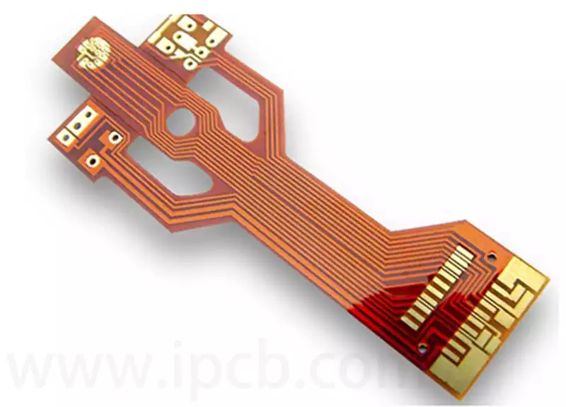
Unlike rigid PCBs, the 4 layer FPC stack has a structure with a flexible substrate at its core, conductive layers for functionality, and insulating layers for protection. A typical structure from outer to inner layers is as follows: Cover film (surface insulation protection) → Copper foil (signal transmission) → Flexible substrate (core support, such as PI or PET) → Copper foil (signal transmission) → Cover film (bottom insulation protection). In some cases, reinforcing layers may be added based on specific requirements. The core thickness is typically controlled between 0.1 mm and 0.3 mm.
Core Advantage of the 4 Layer FPC Stack
The primary advantage of the 4-layer stack is its ability to balance signal transmission capability and flexible bending performance, allowing for the simultaneous transmission of multiple signals, thus meeting the requirements of mid- to high-end electronic devices (such as wearable devices, foldable smartphones, and industrial sensors). The design differences between static and dynamic bending are essentially centered around the stress distribution during bending, necessitating targeted optimization of materials, layer thicknesses, trace layout, and reinforcement methods for the 4-layer stack.
Static bending focuses on long-term stability after bending, while dynamic bending focuses on fatigue resistance after repeated bending. These two design logics are fundamentally different and should not be mixed.
Definitions and Applications of Static vs. Dynamic Bending
Static Bending refers to a one-time bending that maintains a fixed angle for a long time without repeated deformation. Simply put, after bending, the component stays fixed in place, and the bent area is subjected to static stress with no cyclic fatigue. Typical applications include: curved bonding areas in wearable devices (smartwatches, wristbands), fixed routing in automotive electronics, static wiring in industrial equipment, and fixed bending connections in medical devices. In such scenarios, FPCs are required to maintain the bent shape without rebound or damage, with stable signal transmission and no repeated deformation.
Dynamic Bending refers to repeated bending and resetting, involving periodic deformation. The bent area is subjected to dynamic fatigue stress and must resist material aging, trace breakage, and substrate damage caused by cyclic bending. Typical applications include: hinge areas in foldable smartphones (which may fold thousands of times), robotic joint wiring, roller connections in printers, and foldable connections in portable devices. In such cases, FPCs must endure repeated bending, maintain stable signal transmission, and meet the product’s required lifespan (typically ≥100,000 bending cycles).
Design Differences in 4 Layer FPC Stacks
1.Substrate Selection
The substrate is the core support of the 4-layer FPC stack and directly impacts bending performance. The choice of substrate for static vs. dynamic bending primarily focuses on balancing flexibility and fatigue resistance.
For static bending, the substrate selection emphasizes stability after forming, with less emphasis on high flexibility but ensuring that the bent shape does not rebound or crack. PI (Polyimide) is recommended with a thickness of 0.025-0.05 mm. PI’s advantages include high-temperature resistance and dimensional stability, maintaining a fixed angle after bending without rebound or deformation, making it ideal for static bending. The dielectric constant (Dk) should be stable (recommended Dk = 3.0–3.5) to ensure stable signal transmission after static bending, avoiding signal distortion caused by substrate deformation.
For dynamic bending, the substrate selection focuses on fatigue resistance against repeated bending. The key requirement is a substrate with good flexibility and strong anti-aging properties, able to withstand periodic deformation without cracking. High-flexibility PI (modified PI) is recommended with a thickness of 0.012-0.025 mm. This substrate is thinner than that for static bending, offering better flexibility and more even stress distribution during repeated bending. It is also essential to use a fatigue-resistant material, avoiding PET substrates (which have poor fatigue resistance and are more suitable for low-frequency dynamic bending).
2.Copper Foil Thickness
As the core component for signal transmission in FPCs, the thickness of the copper foil directly affects the stability of traces during bending. The thicker the copper foil, the more rigid it becomes, making it more prone to breaking during bending, especially in dynamic bending scenarios.
For static bending, copper foil thickness can be chosen flexibly according to the signal transmission requirements. There is no need to focus excessively on thin copper foil. 18 μm to 35 μm copper foil is recommended. For high signal transmission, 35 μm copper foil is suitable, while for compact products, 18 μm foil can be used. During static bending, the traces experience static stress without cyclic fatigue, so a slightly thicker copper foil will not affect performance, provided the layout is reasonable and the bend area does not have overly dense traces.
For dynamic bending, the focus is on thin and uniform copper foil to reduce stress concentration during bending. 9 μm to 18 μm ultra-thin copper foil is recommended, preferably rolled copper foil (RA copper foil). Rolled copper foil has finer grain structure, better flexibility, and superior fatigue resistance compared to electrolytic copper foil (ED copper foil), which reduces the likelihood of trace breakage during repeated bending. It is important to note that the foil thickness should not be too thin (below 9 μm), as this could negatively impact signal transmission performance. A balance between flexibility and signal transmission should be maintained.
3.Layer Thickness Proportions
The proportion of layer thickness in the FPC 4-layer stack directly influences the distribution of stress during bending. If the layer thickness proportions are imbalanced, stress concentration can occur, leading to substrate damage or trace breakage. This is especially critical in dynamic bending scenarios, where precise control of layer thickness is essential.
For static bending, the layer thickness proportion should be symmetrical to ensure stability after bending without rebound or deformation. A recommended layer thickness proportion (from outer to inner) is: Cover film (0.02 mm) → Copper foil (18–35 μm) → Substrate (0.025–0.05 mm) → Copper foil (18–35 μm) → Cover film (0.02 mm), with an overall thickness controlled between 0.1–0.2 mm. Ensuring symmetry in the cover film and copper foil thickness ensures uniform stress distribution during bending and avoids stress concentration on one side. The substrate thickness is moderate, ensuring stability after forming.
For dynamic bending, the focus is on thinner middle substrate layers, with symmetrical thinner upper and lower layers to reduce stress concentration. A recommended layer thickness proportion (from outer to inner) is: Cover film (0.01–0.015 mm) → Copper foil (9–18 μm) → Substrate (0.012–0.025 mm) → Copper foil (9–18 μm) → Cover film (0.01–0.015 mm), with overall thickness controlled between 0.05–0.1 mm. The thinner central substrate improves overall flexibility, while the thinner upper and lower layers ensure uniform stress distribution during repeated bending, reducing fatigue and extending lifespan.
4.Trace Layout
Trace layout is a critical detail in FPC 4-layer stack design, particularly at bending areas, which directly impacts bending reliability. Poor trace layout can lead to stress concentration during bending, causing trace breakage or signal distortion. The trace layout logic for static and dynamic bending differs significantly.
For static bending, the key is avoiding the bend apex and reducing trace density. Traces near the bend should be laid parallel to the bending direction and avoid being perpendicular to it, as perpendicular traces are more likely to concentrate stress. Traces should not be placed at the bending apex unless necessary, and if traces must be placed there, spacing of at least 0.1 mm should be maintained to reduce trace density and avoid mutual compression during bending. Additionally, for static bending, the trace width can be increased (recommended ≥0.1 mm) to enhance signal stability.
For dynamic bending, the key is to distribute stress and improve fatigue resistance, which is stricter than static bending. First, traces at the bending area must be parallel to the bending direction and never laid perpendicularly. Secondly, trace spacing should be larger (≥0.12 mm) to prevent friction between traces during repeated bending. Thirdly, traces at the bending area should use arc-shaped transitions instead of right-angle turns, which would concentrate stress and cause easy breakage. Lastly, traces in dynamic bending should ideally be placed in the middle layers of the stack, as they experience the least stress, thus reducing fatigue damage caused by repeated bending.
5.Reinforcement Design
Reinforcement design focuses on increasing local rigidity of the FPC to protect key areas. The reinforcement needs for static and dynamic bending differ.
For static bending, reinforcement focuses on maintaining stability after forming. Reinforcement films can be placed in non-bending areas or areas with low bending stress. It is recommended to use PI reinforcement sheets (thickness 0.1–0.2 mm), and these reinforcement sheets should be placed at the ends or fixed positions of the FPC, away from the bending apex, to enhance local rigidity. However, reinforcement sheets should not cover the bend area, as this would affect bending performance and cause substrate damage.
For dynamic bending, reinforcement design focuses on local protection without compromising flexibility. Reinforcement should be minimal, only covering key areas such as solder joints or connectors. It is recommended to use ultra-thin PI reinforcement sheets (thickness 0.05–0.1 mm) with minimal coverage, avoiding any extension to the bending area. Additionally, reinforcement materials should be chosen for their high flexibility to avoid stress concentration during bending, which could lead to issues such as reinforcement sheet detachment or substrate cracking.
Future Trends in 4-Layer FPC Bending Design
With the rapid development of foldable screens, wearable devices, industrial robots, and medical devices, the application scenarios for FPCs are expanding, and the requirements for bending performance are increasing. Static bending now focuses on more precise shaping and thinner thickness, while dynamic bending emphasizes higher bending cycles and more stable signal transmission. These trends are driving 4-layer FPC bending design towards precision, lightweight, and high reliability.
In the future, dynamic bending FPC design will focus on ultra-thin materials and fatigue resistance, with thinner, high-flexibility substrates (such as 0.01 mm modified PI) and ultra-thin rolled copper foils (such as 6 μm), combined with new lamination processes to reduce stress concentration and extend bending cycles (expected to exceed 500,000 cycles). Static bending FPC design will emphasize integrated shaping and precise dimensions, combining 3D forming processes for more complex curved bonding areas to meet a broader range of product requirements.
With the integration of AI and automation technologies, FPC 4-layer bending design will achieve smart calculation, automatically optimizing layer thickness proportions, trace layout, and reinforcement design based on simulated bending stress. This will reduce human error, improve design efficiency, and enhance reliability. For PCB manufacturers, mastering the design differences between static and dynamic bending and staying ahead of industry trends is essential to gaining a competitive edge in the FPC market.