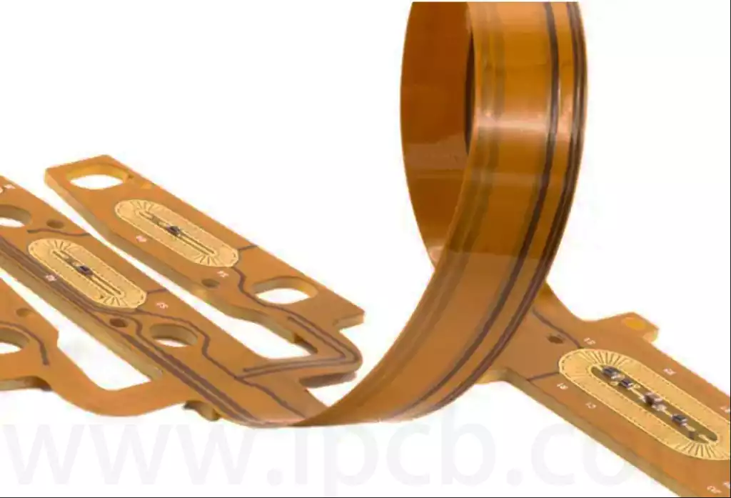
What is coverlay in fpc?FPC coverlay is polymer film made from materials such as polyimide (PI), primarily used to protect and insulate the external circuits of flexible PCB. FPC coverlay is the earliest and most widely used technology in the application of cover layers for flexible printed circuit boards.
FPC coverlay primarily serves to protect copper foil circuits and provide insulation. They prevent circuits from oxidation, scratching, and chemical corrosion, ensuring the long-term stable operation of FPC pcb. The adhesion and heat resistance of the cover film are also important considerations, as they impact the production process and reliability of FPC boards.
The FPC coverlay is produced by applying the same adhesive used on copper-clad laminate substrates to the same type of film, creating a semi-cured adhesive layer. It is supplied by manufacturers of copper-clad laminates. When supplied, the adhesive film is covered with a release film (or paper). The semi-cured epoxy-based adhesive gradually cures at room temperature, so it should be stored at low temperatures. Printed circuit manufacturers should keep it in a refrigerator at around 5°C until use or have it shipped by the manufacturer before use. Generally, material manufacturers guarantee a shelf life of 3–4 months, which can be extended to 6 months under refrigerated conditions. Acrylic adhesives do not cure at room temperature. Even if not stored under refrigeration, they remain usable for over six months. However, the lamination temperature for such adhesives must be very high.
FPC coverlayer materials are primarily divided into two categories: coverlay film and flexible solder mask.
FPC coverlay is a material composed of polyimide (PI) film combined with thermosetting adhesives such as epoxy resin or acrylic resin. It is the most widely used coverlayer material in flexible PCBs, particularly offering significant advantages in high-reliability and harsh environmental conditions.
Advantages:
Excellent mechanical properties: PI film has extremely high tensile strength and flexibility, capable of withstanding repeated bending.
Excellent heat resistance: PI film has a thermal decomposition temperature exceeding 400°C, suitable for high-temperature soldering processes.
High electrical insulation performance: PI film has an insulation strength exceeding 100 kV/mm, making it suitable for high-voltage applications.
Chemical corrosion resistance: It exhibits good resistance to acids, alkalis, solvents, and other chemicals.
Disadvantages: High cost, especially in large-scale production, which significantly increases manufacturing costs. Complex processing techniques require precise positioning and high-temperature lamination equipment.
Flexible solder mask ink (Flexible Solder Mask) Flexible solder mask ink is a liquid material applied to the surface of flexible PCBs via screen printing or spraying processes, followed by UV curing or thermal curing to form a protective layer.
Advantages: High processing flexibility: Suitable for complex patterns and small-batch customised production.
Low cost: Compared to cover films, solder mask ink has lower material and processing costs.
Thin design: The thickness of the solder mask ink layer is typically thinner than that of cover films, facilitating the design of extremely thin flexible circuits.
Disadvantages:
Weak mechanical properties: Prone to cracking or peeling under repeated bending, unsuitable for high dynamic stress environments.
Limited heat resistance: Typically only capable of withstanding short-term high-temperature soldering.
Poor environmental adaptability: Moisture resistance and chemical stability are inferior to cover films.

FPC coverlayer design requirements
- Minimise the number of coverlayer openings (cover access). For example, some vias and metallised holes can be designed as fully covered forms (similar to solder mask without openings).
- When creating small windows, prefer circular coverlayer openings, followed by elliptical ones, and avoid square openings.
FPC coverlayer Processing Capabilities
- The smallest drill holes or punch holes for the coverlayer are 0.25mm (subject to variation based on the manufacturer’s drilling capabilities).
- The edge spacing of cover film holes should be greater than 0.25mm (PC-2223 specification: if smaller than this value, alternative processes such as laser cutting must be used). When designing high-density board spacing, if the coverlayer window spacing cannot meet the 0.25mm (10mil) requirement, use an overall cover film window around the pad or solder paste ink to achieve compliance.
FPC Coverlayer Solder Pad Design
In high-performance applications, a coverlayer solder pad design (referred to as a ‘solder mask defined pad’) can be used to enhance pad adhesion and improve reliability. Generally, the pad should be at least 0.36mm larger than the cover film window (0.18mm larger on each side).
The fpc coverlayer on flexible printed circuits (FPC) plays a critical role in protecting and insulating the external circuits of FPCs, and its performance directly affects the reliability and service life of the circuit board. Selecting the appropriate cover film material is crucial. However, its high cost and complex processing procedures are factors that must be considered.


