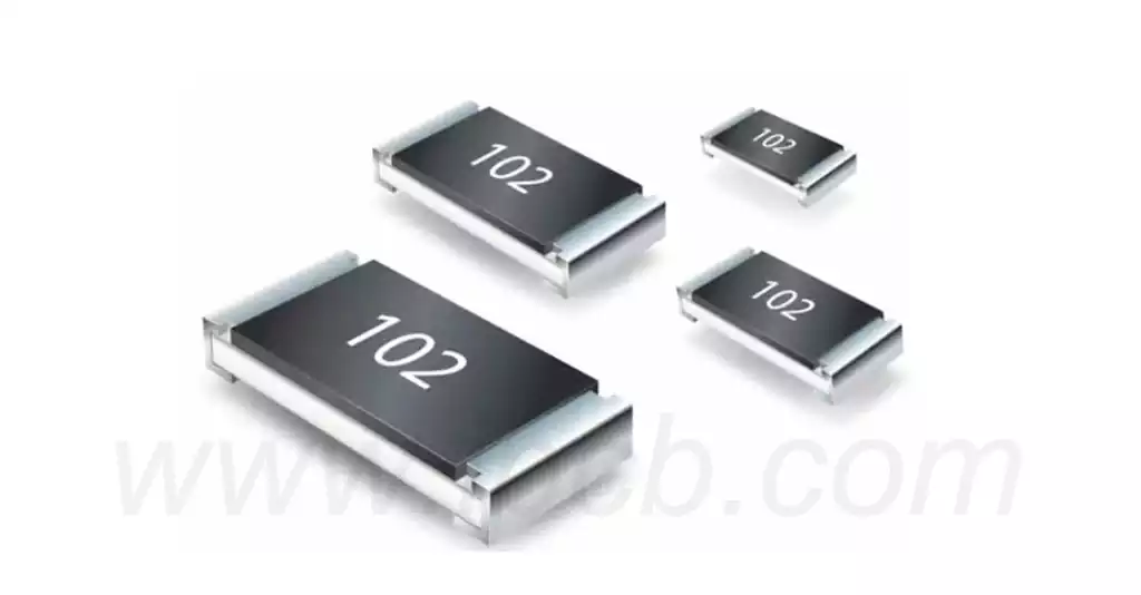
What is a chip resistor? A chip resistor, also known as a surface mount resistor (SMD Resistor), is a type of resistor designed for surface mount technology (SMT). Compared to traditional leaded resistors, SMD resistors are designed without leads, allowing them to be attached directly to the surface of a printed circuit board (PCB).
Key Features:
Small size and light weight;
Adaptable to reflow and wave soldering;
Stable electrical performance and high reliability;
Low assembly cost and matching with automatic mounting and pasting equipment;
High mechanical strength and superior high frequency characteristics.
Chip resistors are mainly composed of four major parts:.
(1) substrate: the substrate material is generally 96% aluminum oxide ceramic. In addition to good electrical insulation, the substrate should also have excellent thermal conductivity at high temperatures. Electrical properties and mechanical strength and other characteristics. It is also required that the substrate is flat and accurately scribed. Standard to fully ensure that the resistance. Electrode paste printing in place.
(2) Resistive film: printed on a ceramic substrate with a certain resistivity of the resistive paste, and then sintered. Resistive paste is generally used ruthenium dioxide.
(3) Protective film: the protective film will be covered on the resistive film, mainly to protect the resistor body. On the one hand, it plays the role of mechanical protection, on the other hand, the surface of the resistor body has insulating properties, to avoid resistance and neighboring conductors in contact with the failure. In the process of electrodes in the middle electrode, can also prevent the electrodes on the resistance film erosion and lead to resistance performance decline. Protective film is generally a low melting point of the glass paste, sintered by printing.
(4) Electrodes: is to ensure that the resistor has good weldability and reliability, generally three-layer electrode structure: inside. Middle. Outer electrode. The inner electrode is connected to the internal electrode of the resistor body, the electrode material should be selected and the resistive film contact resistance is small, and the ceramic substrate combination of strong and good chemical resistance, easy to implement plating operations. Generally sintered with silver-palladium alloy printing. The middle electrode is nickel-plated layer, also known as the barrier layer. Its role is to improve the heat resistance of the resistor during welding and to buffer the thermal shock during welding. It can also prevent the migration of silver ions to the resistance film layer, to avoid causing the phenomenon of internal electrode erosion (internal electrode is melted by the solder) outer electrode tin-lead layer, also known as the weldable layer. Its role is to make the electrode has good weldability, to extend the preservation period of the electrode. Generally made of tin-lead alloy plating.
Chip resistor production process can be summarized in the following steps.
- Material Preparation Resistor Paste: Select the resistor paste that meets the requirements to ensure the accuracy and stability of the resistance value. Ceramic substrate: select the ceramic substrate with high insulation and high thermal stability as the carrier of the resistance. Conductive silver paste: used in the production of resistance electrodes, requires good conductivity, strong adhesion. Protective film material: used for the insulation protection of the resistor and prevent environmental erosion.
- Ceramic substrate treatment of ceramic substrate cleaning, drying and other processing to ensure that the substrate surface is clean, no oil and impurities.
- Resistor paste printingPrint the resistor paste on the surface of ceramic substrate according to the design pattern to form a resistive film layer.
- Drying and curing will be printed resistive film layer for drying and curing treatment, so that it reaches a certain hardness and stability.
- Cutting and sortingThe cured ceramic substrate is cut according to the set size, and the resistance value is sorted and tested to ensure the quality of the product.
- Conductive silver paste printingThe conductive silver paste is printed on the two ends of the resistive film layer to form electrodes for circuit connection.
- Protective film coatingProtective film material is coated on the resistor and electrode surfaces to improve the weather resistance and stability of the product.
- Drying and curing of the coated protective film for drying and curing to ensure the integrity and adhesion of the protective film.
- Appearance inspection and testingAppearance inspection and resistance value testing of the finished product to ensure that the product meets the quality requirements.
Chip resistors are widely used in many fields, including but not limited to:
Consumer electronics: such as smart phones, tablets and home appliances, chip resistors are used for signal processing and current limiting.
Industrial equipment: In automated control systems, chip resistors are used in sensor and actuator circuits.
Communication equipment: In network equipment and wireless communication systems, chip resistors are used for signal conditioning and filtering functions.
Automotive Electronics: Chip resistors are used for various types of sensors and control modules in the electronic control systems of modern automobiles.
Chip resistors can be categorized into carbon film resistors, metal film resistors, thick film resistors, and metal oxide film resistors based on their materials. Chip resistors of different materials have significant differences in resistance values and temperature coefficients. These differences affect their application and performance in electronic circuits.
- Carbon Film Resistors
Carbon film resistors are mainly made from organic materials by thermal decomposition technology. They usually have low production cost and moderate performance. They are suitable for general electronic applications, but their accuracy and temperature coefficient are relatively poor for cost-sensitive projects. - Metal Film Resistors
Metal film resistors are manufactured using metal film technology and offer higher accuracy and smaller temperature coefficients. They also outperform carbon film resistors at very high frequencies. Metal Film Resistors are widely used in high precision electronic devices. - Thick Film Resistors
Thick film resistors are coated with a thicker layer of material and usually have very good high temperature resistance and can withstand high temperatures of several hundred degrees Celsius without affecting performance. They are suitable for use in high power and high temperature environments, and are often used in power supply and filter designs. - Thin Film Resistors
Thin film resistors have a thin film layer, high precision and a small temperature coefficient, and are suitable for demanding electronic equipment, such as precision instruments and high-frequency circuits. They are usually more expensive than thick film resistors, but excel in small size and high precision requirements. - Metal Oxide Film Resistors
Metal Oxide Film Resistors are another type of resistor that excels in high temperature resistance and stability for critical applications. They can be used in environments that require high stability, such as automotive electronics.
Selecting the right chip resistor requires consideration of several key parameters such as resistance value, power, accuracy, temperature coefficient and package type. By comprehensively evaluating these factors, you can ensure that the selected resistor achieves optimum performance and reliability in the desired application.
- Determining Resistance Value
The first step in selecting a chip resistor is to understand the resistance value required by the circuit. This parameter directly affects the amount of current and the overall efficiency of the circuit. The resistance value should be selected according to the circuit design requirements. - Consider power and rated voltage
During the selection process, the power rating of the chip resistor needs to be evaluated to ensure that it can withstand the maximum power that may be present in the circuit. If the power of the resistor is insufficient, it may lead to overheating and damage. Attention should also be paid to the voltage rating to ensure that the resistor will not breakdown during operation. - Accuracy and Temperature Coefficient
The tolerance and temperature coefficient of the resistor are important parameters for some high-precision applications. The smaller the tolerance, the more stable the resistor’s performance under certain conditions. The temperature coefficient determines the stability of the resistance value with temperature change. The smaller the temperature coefficient, the more stable the resistor can keep its resistance value. - Selection of Package Type
Chip resistors are available in a variety of package types, each of which is suitable for different electronic products. Engineers need to choose the right package size according to the space constraints and layout requirements of the PCB design, the common ones are 0402, 0603 and 0805.
As an indispensable and important component in modern electronic equipment, chip resistors are widely used in various electronic products by virtue of their miniaturization, high reliability and high performance. Resistors made of different materials exhibit significant differences in resistance values and temperature coefficients, enabling designers to select the most suitable product according to specific application requirements. Whether in consumer electronics, industrial equipment, communications and automotive electronics, the proper selection and application of chip resistors can significantly improve circuit performance and stability.