Circuit board drawing is a crucial part of electronic engineering design, which not only relates to the functionality of the circuit, but also directly affects the performance and reliability of the circuit. The following will introduce the basic process of circuit board drawing and some key considerations.
The basic process of circuit board drawing usually includes the following steps:
Requirements analysis: Before starting to draw, a requirements analysis is first conducted to clarify the functions and specifications of the circuit board.
Schematic design: After clarifying the requirements, draw the schematic diagram of the circuit, labeling the components and their connection relationship.
Physical structure design of the circuit board: According to the schematic diagram for the physical layout of the circuit board, to determine the size and shape of the circuit board.
PCB Layout: Reasonable placement of components on the circuit board according to functional logic to reduce signal interference and simplify wiring.
Wiring: use the design software to carry out the signal line and power line wiring work, pay attention to the length and width of the signal line and impedance matching and other factors.
Wiring Optimization: After completing the initial wiring, perform wiring optimization and silkscreen design to ensure the clarity and functionality of the board.
Check and Output: After all steps are completed, network analysis and DRC (Design Rule Check) are performed to ensure that the wiring is error-free before outputting the light drawing file.
8 Ways to circuit board drawing schematics
- Select electronic components such as integrated circuits, transformers, transistors, etc., which are bulky, have many pins and play a major role in the circuit, and then draw from the selected reference pins to minimize errors.
- If the PCB is labeled with component numbers (e.g. VD870, R330, C466, etc.), the drawing should be used since these serial numbers have specific rules and components with the same Arabic numerals following the letters of the alphabet are the same functional unit. Correctly distinguishing components of the same functional unit is the basis of drawing layout.
- If the serial numbers of the components are not marked on the printed circuit board, it is better to number them yourself to facilitate analysis and proofreading. When designing printed circuit board components, manufacturers usually lay out components of the same functional unit relative to each other in order to minimize copper-clad wiring. Once a device with a core function is found, other components of the same functional unit can be found as soon as it is located.
- Correctly distinguish between ground, power and signal wires on a pcb substrate. Take the power supply circuit as an example, the negative terminal of the rectifier connected to the secondary of the power transformer is the positive terminal of the power supply. Large-capacity filter capacitors are usually connected between ground and ground, and the capacitor case has polarity markings. The power and ground wires can also be found from the three-terminal regulator pins. When factory wiring of printed circuit boards is done to prevent self-excitation and to combat interference, the ground copper foil is usually set to be the widest (high-frequency circuits usually have a large area of ground copper foil), with the power supply copper foil being the second, and the signal copper being used. Foil is the narrowest. In addition, in electronic products with analog and digital circuits, printed circuit boards often have their grounds separated to form separate ground grids, which can also be used as a basis for identification and judgment.
- To avoid over-wiring of components, circuit diagrams have wiring that crosses and interlaces, resulting in a confusing image. and power and ground lines can be used for a large number of terminal markers and ground symbols. If there are many components, the unit circuits can be drawn individually and then combined.
- When sketching, it is recommended to use transparent tracing paper and use a multi-color pen to draw ground, power, signal, components, etc. in color. When modifying, gradually deepen the color, so that the drawing is visually striking, in order to analyze the circuit.
- Proficiency in the basic composition of some unit circuits and classic drawing methods, such as rectifier bridges, voltage regulator circuits and operational amplifiers, digital integrated circuits. These unit circuits are drawn directly into the framework of the circuit diagram, which can improve the drawing efficiency.
- When drawing circuit diagrams, you should try to find the circuit diagrams of similar products for reference, so that you can do more things with fewer resources.
Circuit board drawing Precautions
- Planning the layout of the circuit board
Before PCB drawing, you need to plan the layout of the circuit board. When designing the layout, pay attention to the size of the board, the size and location of components, and the layout of all pins. In the layout, it is best to place larger components at the edge or corner of the board to save space. - Select the appropriate board size
It is very important to choose the appropriate board size. If the board size is too small, it will make it difficult to layout components and may not be able to accommodate the required distances and lines after the layout is completed. If the board size is too large, the equipment will become more expensive and space will be wasted. - Draw clear circuit diagrams
Circuit diagrams should be clearly visible for study. Correctly obtaining the inter-board distances of components and drawing clear distance lines is the key to drawing a circuit board. On the circuit diagram, all electrical connections should be readable and symbols should be used accurately to represent components. - Select the appropriate line width
When choosing line widths in circuit board drawing, consider the electrical degrees of different parts of the circuit on the board. When line widths are too small, they cannot withstand high currents, which can cause deformation and, in the case of insufficient distribution, hot spots, where high currents pass through small wires. On the other hand, wire widths that are too large are not desirable because they cannot carry enough current and take up too much space. - Maintaining continuity in drawing circuits
In circuit board drawing, it is necessary to keep drawing the circuit continuously. This means maintaining good connectivity between the different stages of PCB drawing. Each stage of PCB drawing requires minor adjustments before the next stage of PCB drawing. Changes need to be made to confirm that the PCB has been correctly adjusted. - Check PCB board dimensions
When checking the PCB board dimensions, it is important to make sure that the PCB board dimensions meet the requirements of the circuit. Because PCBs are made in accordance with the actual circuit design, problems can arise if the PCB board dimensions do not meet the requirements, for example, certain circuits cannot be adapted to the components on the board. - Check and control the thickness of PCB
The thickness of the PCB board should never be out of range, as this can affect the line spacing data and the metal line spacing data. In addition, make sure that the design of the board meets the requirements of the chosen material to ensure the quality of the board production. If the PCB is actually thicker than it was designed to be, this will affect the PCB layout as component distances will vary due to the thickness not being taken into account.
When circuit board drawing, make sure that the component layout is reasonable and effective:
- Basic principles of component layout
When circuit board drawing, a reasonable component layout is the key to ensure the performance of the circuit.Components should be arranged according to the functional requirements of the circuit in order to shorten the signal transmission path and reduce interference and loss.Following these basic principles can significantly improve circuit board reliability and engineering manufacturability. - Reasonable planning of board shape and size
Before starting the layout, you first need to determine the shape and size of the PCB.This will help to place components in appropriate locations for effective routing and signal management. Ensure that the mapped board shape is planned before placing the components in a reasonable position to meet the design requirements and manufacturing needs. - Component Orientation and Arrangement
To improve soldering stability, ensure that similar components are placed in the same direction during layout. This will help to achieve a more efficient and error-free soldering process. In addition, try to avoid placing smaller components behind larger ones to avoid affecting the soldering and subsequent operations. - Reasonable Arrangement of Signal and Power Alignments
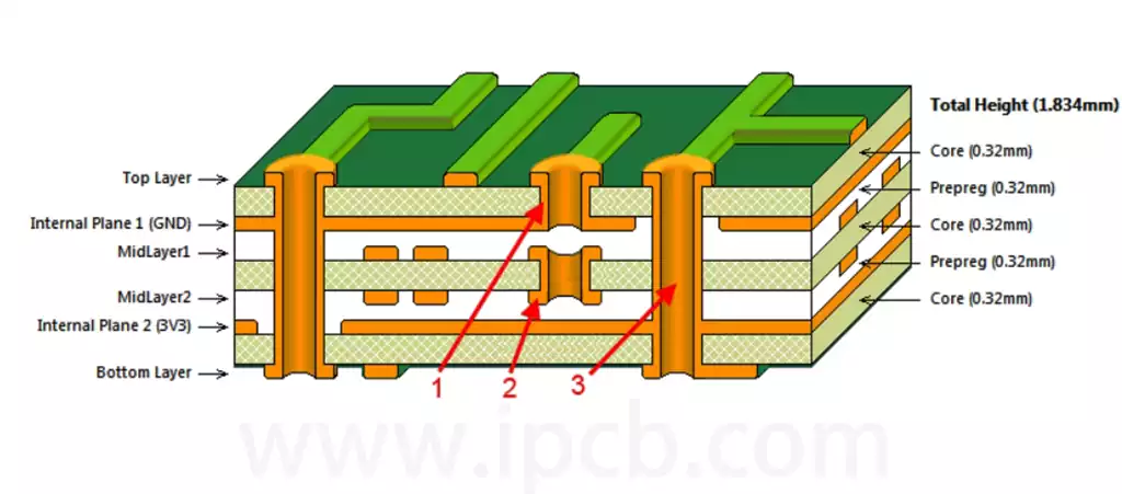
Reasonable layout of the power, ground and signal alignments can ensure a clean and interference-free signal path. It is recommended that the power supply layer plane is placed inside the circuit board and kept symmetrical and centered to reduce the path impedance and signal interference. When connecting signal lines, the shortest possible path should be used to avoid signal integrity issues. - Perform layout optimization and iteration
Once the layout is complete, it is important to periodically review and optimize the design. Using Electrical Rule Checking (ERC) and Design Rule Checking (DRC) tools can help ensure that the layout meets all requirements and possible problems are adjusted in a timely manner. Continuous improvement of the PCB layout can help improve the overall performance and reliability of the circuit.
Circuit board drawing is a crucial step in electronic design, involving schematic design, component layout, wiring and optimization. Through proper planning, accurate labeling, and following best practices, you can effectively improve the performance and reliability of your board. Mastering these key points will help you design high-quality circuit boards.