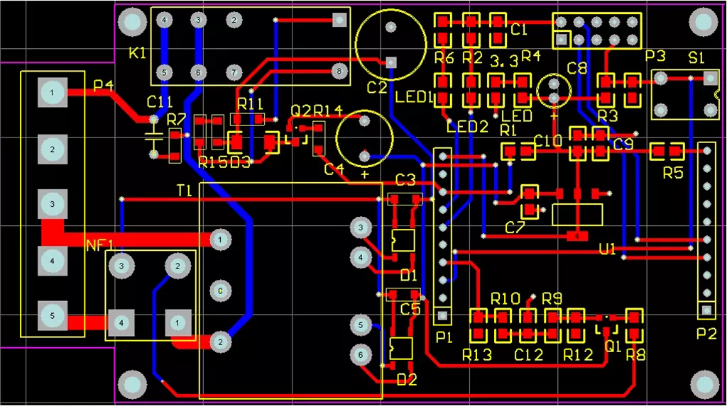
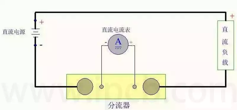
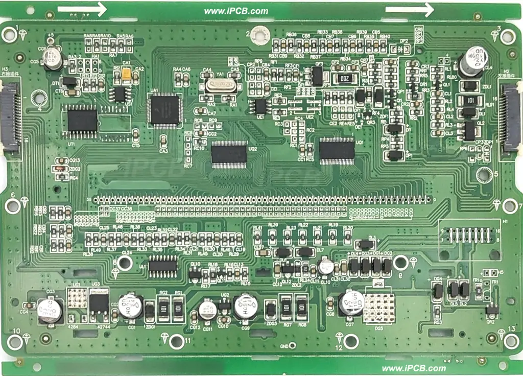
A circuit diagram is a pictorial representation of the connections of a circuit using graphical symbols and lines. It is a combination of specific symbols and lines that clearly shows how the electronic components Q are connected, where the current flows, and how the circuit works.
Circuit diagrams can be divided into different types such as schematics, wiring diagrams and assembly diagrams. Schematic diagrams are mainly used to represent the working principle and signal flow of a circuit, usually without considering the actual physical layout; wiring diagrams focus on showing the wiring of the circuit on the actual circuit board; and assembly diagrams are used to guide the assembly process of an electronic device.
Elements of a circuit diagram
- Electronic Component Symbols
The core component of a circuit diagram is the electronic component symbol. Each electronic component has a unique diagram that depicts its role in the circuit and its characteristics. Common electronic component diagrams include resistors, capacitors, inductors, diodes, transistors, and integrated circuits.
For example, the resistor’s diagram is a rectangle, which will be marked above the resistance value; capacitor’s diagram consists of two parallel line segments, connected by a curve in the middle, symbolising the capacitor’s two poles; and the diode’s diagram is a triangle, the tip of which extends a line to indicate the positive pole of the diode. - Conductive wires
Conductive lines are responsible for interconnecting the electronic component diagrams to show the electrical connection between them. These lines can be in the form of straight, curved or zigzag lines, and the thickness and colour of the lines are often used to distinguish between different electrical properties.
In circuit diagrams, conductive lines are often shown as solid lines to represent the paths through which current can flow, while dotted lines may be used to indicate control signals or other types of special connections. In addition, arrows may be attached to the conductive lines to indicate the specific direction of current flow. - Power supply and grounding
The power supply is the energy base that drives the operation of the circuit. It is usually presented as a circle or rectangle with the voltage value and the positive and negative polarity labelled on it. Ground represents the potential reference point in the circuit and is usually represented by a triangle or a special ground symbol.
In the layout of circuit diagrams, the symbols for power supply and earth are often placed at the edges of the drawing or in specific locations so that they can be easily recognised and connected. - Markings and explanatory texts
Markings and explanatory text play an essential role in circuit diagrams, providing key information about the parameter details of electronic components, model identification, functional description and the mechanism of the circuit. This information can be presented in a variety of forms, such as textual descriptions, numerical expressions,or special symbols, and is usually placed in the immediate vicinity of the electronic component symbols or in a free space on the drawing.
For example, the marking of a resistor may cover details such as its resistance value, power rating,accuracy class, etc., while the marking of a capacitor may contain important parameters such as capacitance value, voltage rating, and polarity.In addition,circuit diagrams may be interspersed with explanatory text that describes the circuit’s mechanism of operation, special design features, or precautions to be taken when operating the circuit.

Functions of PCB Circuit Diagrams
Design Cornerstone: Schematic diagrams form the cornerstone of circuit design,with which engineers plan the basic structure of the circuit and the connection between components, providing an intuitive and easy-to-adjust platform for designing efficient and responsive circuits.
Fault Detection and Repair Basis: When an electronic product malfunctions, the schematic becomes a key reference for technicians to locate the problem and repair it, helping them to quickly find the point of failure and implement a fix.
Manufacturing and Assembly Guidelines: Schematics provide detailed connection and layout guidelines for PCB manufacturing and electronic component assembly, ensuring that every aspect of the production process is accurate.
Medium of communication:As a universally applicable language, schematic diagrams facilitate effective communication between people from different backgrounds and areas of expertise.Whether they are electronic engineers,production personnel or project managers,schematic diagrams enable them to quickly grasp the design intent of the circuit and the means of realisation.
Educational and Training Resources:For students or practitioners in the field of electrical engineering,schematics are a key resource for learning circuit design, analysis and troubleshooting, helping them to master the basic principles of circuits and practical application skills.
Intellectual property protection tool: schematic diagrams record the design ideas and implementation details of circuits, which is an important document to safeguard innovative achievements and prevent intellectual property infringement.
As a core tool in the field of electronics,circuit diagram not only plays a vital role in circuit design,manufacturing,maintenance, teaching and intellectual property protection, but also serves as a bridge connecting people in different professional fields. With its unique graphic symbols and line language, it clearly reveals the mystery of circuits and makes the complex electronic world orderly and easy to understand.


