Introduction
In modern electronics manufacturing, flexible printed circuits (FPCs) have become a key technology for connecting miniaturized, high-performance electronic systems. As electronic products continue to evolve toward thinner, smarter, and more multifunctional designs, traditional rigid circuit boards are increasingly unable to meet the demands of complex spatial layouts and dynamic environments. In contrast, FPCs, with their lightweight, flexible, and foldable properties, have become a key option for meeting the design requirements of next-generation products.
Among the many FPC manufacturing processes, etched FPC is the most representative. Etched FPCs involve removing excess copper foil through chemical etching or other precision removal techniques to form the desired conductor pattern. This process not only determines the accuracy and reliability of the circuits but is also a core step in achieving high-density interconnects and complex designs in flexible circuits.
The value of etched FPCs lies primarily in the following aspects:
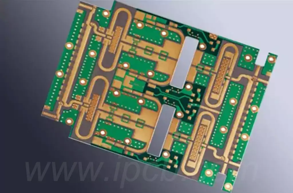
High-definition circuits: The etching process enables extremely narrow line widths and spacing, supporting high-speed signal transmission and high-density wiring.
Meeting Complex Design Requirements: FPC’s inherent bendability and foldability, combined with an etching process, enables complex three-dimensional assembly requirements.
Wide Applications: From smartphones and wearables to automotive electronics, medical devices, and aerospace, etched FPC offers irreplaceable value.
Driving Technological Evolution: With the rise of 5G/6G communications, artificial intelligence, and new energy vehicles, the requirements for the precision and performance of flexible circuit boards are becoming increasingly stringent, and etched FPC serves as the bridge that enables these technologies.
Thus, to truly understand the core of flexible circuit boards, a deep dive into etched FPC is essential. From its process principles and material selection to design challenges, manufacturing processes, applications, and future trends, every aspect reflects the electronics manufacturing industry’s continuous pursuit of high performance and reliability.
Process Principles of Etched FPC
In the manufacturing process of flexible circuit boards (FPCs), the way the circuits are formed directly determines the product’s precision, performance, and reliability. The core of etched FPCs lies in the “etching” process, which transfers the designed circuit pattern to the substrate surface through the precisely controlled removal of copper foil.
Basic Principles of Etching
Etching is a “subtractive” process. A layer of resist (such as dry film or photoresist) is first applied to the copper-clad substrate surface. A photolithography step then develops the circuit pattern, exposing the unneeded copper foil. A chemical solution (commonly copper chloride or copper sulfate) is then used to dissolve and remove the exposed areas, leaving only the conductive traces.
The key objectives of this process are:
Ensuring uniform etching depth without overetching or residual copper; accurately reproducing the designed pattern to avoid circuit deformation; and maintaining consistency and repeatability during mass production.
Comparison of Chemical Etching and Laser Etching
In the practical application of etched FPCs, chemical etching is the most common process. However, with the increasing demand for finer circuitry, laser etching is becoming a supplementary method.
Chemical Etching:
Advantages: Mature process, suitable for large-scale production, and low cost;
Disadvantages: Susceptible to problems such as insufficient etching factor and uneven line edges, which limits the processing of ultra-fine circuits.
Laser Etching:
Advantages: High precision, capable of processing extremely narrow line widths and complex patterns, particularly suitable for high-density interconnects (HDI) and specialized materials;
Disadvantages: High cost, relatively low processing efficiency, primarily used for high-end products or small-batch production.
In actual production, chemical etching remains the mainstream process, but laser etching is gradually demonstrating its unique advantages for products with extremely high requirements (such as medical implants and aerospace electronic modules).
Key Steps in Conductor Pattern Formation
A standard etched FPC process generally includes the following steps:
Substrate Preparation: Select a suitable copper-clad polyimide (PI) or polyester (PET) material and ensure that the copper foil surface is clean and free of oxidation.
Resist Coating: Apply photoresist to the copper foil and form the desired circuit pattern through a photolithography process.
Development and Etching: After development, the unwanted areas are exposed and then etched away with a chemical solution; this process requires strict control of time and concentration.
Resist Stripping: Removes residual resist to reveal a complete circuit pattern.
Post-Processing: Cleans, dries, and applies surface protection to prevent oxidation of the copper circuits.
This process may seem simple, but it requires extremely high precision in every step, especially in controlling etching time and solution composition. Even the slightest mistake can lead to circuit defects, shorts, or opens.
Key Control Factors in the Etching Process
Etching Factor: This reflects the ratio of etch depth to lateral diffusion and is a key indicator of circuit quality.
Copper Thickness Selection: Thicker copper foil makes etching more difficult, also limiting the minimum line width and spacing; therefore, ultra-fine circuits often use a copper thickness of 9μm or 12μm.
Solution Flow Rate and Temperature: These determine the uniformity and rate of etching; excessively high or low flow rates can affect the final circuit accuracy.
Mask Material Performance: Photoresists with high resolution and excellent corrosion resistance are essential for high-definition circuits.
In summary, the etched FPC process is not just a material removal process, but also a sophisticated engineering control system. Only through precise control of materials, equipment, and process parameters can the highly reliable flexible circuits required for high-end electronic products be manufactured.
Material Selection and Performance Requirements
The stability and reliability of etched FPCs depend heavily on the selection and combination of materials. Flexible circuit boards are essentially a composite of multiple layers of materials, including a substrate, a conductive layer, an adhesive, and a coverlay. Each material significantly impacts the performance of the final product.
Copper-Clad Substrate Selection
The substrate for flexible circuit boards is typically polyimide (PI) or polyester (PET).
Polyimide (PI)
Advantages: High-temperature resistance, chemical resistance, and excellent mechanical properties.
Features: Suitable for applications requiring high reliability and long-term stability, such as automotive electronics and aerospace.
Polyester (PET)
Advantages: Low cost, high transparency, and good flexibility;
Disadvantages: Poor heat resistance, limiting its use in high-temperature soldering and high-frequency applications.
For etched FPCs, most high-end applications choose PI substrate because it maintains good dimensional stability and corrosion resistance during the etching process.
Copper Foil Thickness and Characteristics
Copper foil is the conductive layer of the FPC, and its thickness directly affects the controllability of the etching process and the precision of the final circuit.
Common copper thicknesses: 9μm, 12μm, 18μm, and 35μm. Thinner copper foils are easier to form fine circuits, but mechanical strength decreases. Thicker copper foils are suitable for high current applications, but are more difficult to etch and prone to line deformation.
Therefore, when designing etched FPCs, it is necessary to strike a balance between electrical performance and processing difficulty based on product requirements.
The Role of Adhesives
The adhesive layer is used to connect the copper foil to the substrate or to provide interlayer bonding in multilayer FPCs.
Common Materials: Acrylic, Epoxy, Modified Resin;
Performance Requirements: High Bond Strength, Heat Resistance, Low Moisture Absorption;
Technology Trend: Some high-end applications utilize adhesive-less substrates to reduce warping and reliability issues caused by thermal expansion discrepancies.
In etched FPCs, the adhesive layer must prevent delamination during etching and subsequent processes, otherwise circuit stability will be compromised.
Coverlay Protection
Coverlays typically consist of a polyimide film and adhesive. They cover the circuit surface, providing insulation, shielding, and mechanical protection.
Function: Protects circuits from damage caused by moisture, chemicals, and mechanical stress.
Requirements: Heat resistance and flexibility, while maintaining solderability during laser windowing.
For high-frequency applications, some products utilize liquid photoimageable solder mask (LPI) instead of traditional coverlay to improve electrical performance.
The Impact of Material Properties on Etching
During the etched FPC manufacturing process, material properties directly impact the etching results:
Copper foil surface roughness: A rough surface facilitates adhesion, but may affect etching accuracy in fine circuits.
Substrate dimensional stability: A PI substrate effectively prevents deformation caused by temperature and chemical reactions during the etching process.
Chemical corrosion resistance: This determines whether the substrate can withstand multiple cleaning and etching processes.
Heat resistance: This impacts reliability during subsequent soldering and assembly.
Practical Considerations for Material Selection
Different application areas have different material selection criteria for etched FPCs:
Consumer electronics: These prioritize cost and lightweight design, often using 12μm copper thickness and PI substrates.
Automotive electronics: These prioritize high-temperature resistance and reliability, preferring adhesive-free substrates and high-Tg cover films.
Medical devices: These require extremely high biocompatibility and fine circuit processing capabilities, and the materials must meet stringent international certifications.
Aerospace: These applications require not only lightweight design but also resistance to extreme environments (radiation, vacuum, and temperature fluctuations).
In summary, the successful manufacturing of etched FPCs relies not solely on the etching process itself; the proper selection of materials and performance control are equally crucial. It can be said that materials are the foundation of etched FPCs, while the process is the means to achieve the design goals.
Design Considerations and Technical Challenges
In practical applications, etched FPCs must meet the multiple requirements of lightweight, thin, flexible, and highly reliable. Therefore, multiple factors, including electrical performance, mechanical properties, and manufacturing process limitations, must be comprehensively considered during the design phase. Failure to properly design can lead to uneven etching, circuit failure, and even reduced overall reliability during the subsequent manufacturing process.
Limitations on Line Width and Spacing
In etched FPCs, the minimum line width and spacing are affected by multiple factors:
Copper thickness: The thicker the copper, the more severe the undercutting effect during etching, limiting the minimum line width;
Etching factor: Ideally, the vertical and lateral etching rates should be balanced, but achieving perfect consistency in practice is difficult, resulting in pattern distortion;
Process capability: Currently, mainstream chemical etching can consistently achieve 50μm/50μm (line width/line spacing), with some high-end processes even capable of achieving less than 25μm.
Therefore, when developing circuit diagrams, design engineers need to appropriately set parameters based on the manufacturer’s process capabilities to avoid overly challenging limits.
Balancing Flexibility and Reliability
The core advantage of FPCs lies in their flexibility, but there is an inherent conflict between flexibility and mechanical strength:
Excessively fine lines can break when repeatedly bent;
Excessively thick copper foil or adhesive layer reduces flexibility, making it unsuitable for dynamic applications.
To address this issue, designers typically employ the following approaches: using stiffeners or reinforcements in bend areas to distribute stress; avoiding critical circuits as much as possible in bend areas or adding redundant circuits; and finding the right balance between bend radius and copper thickness.
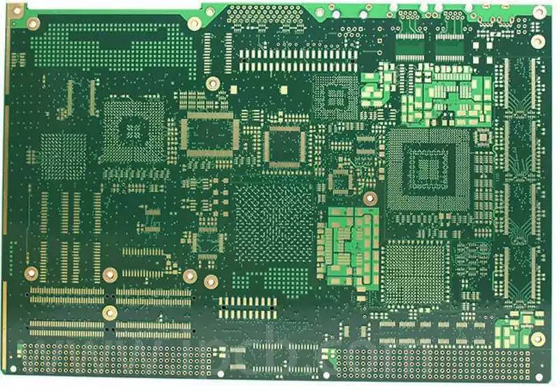
Multilayer FPC Alignment and Etching Challenges
With the increasing demand for high-density interconnects in electronic products, multilayer FPCs have become increasingly popular.
However, multilayer structures present new challenges:
Inter-layer alignment accuracy: Thermal expansion and contraction of the substrate can easily cause misalignment when stacking multiple layers, affecting circuit connectivity.
Differential etching: Different layers have varying copper thicknesses and circuit densities, requiring controlled etching parameters. Otherwise, overetching one layer while underetching another can occur.
Thus, manufacturing multilayer etched FPCs not only places higher demands on design precision but also tests the factory’s production equipment and experience.
Signal Integrity and Electrical Performance
With the increasing prevalence of high-speed transmission and high-frequency applications, FPCs must not only ensure mechanical reliability but also electrical performance:
Impedance Control: In high-speed signal lines, impedance consistency must be maintained by controlling line width, dielectric thickness, and dielectric constant.
Crosstalk: Close line spacing can lead to electromagnetic coupling interference, affecting signal quality.
High-Frequency Loss: Poor material dielectric properties increase signal attenuation, limiting the application frequency.
To this end, design engineers typically use simulation tools (such as SI/PI simulation) to optimize and ensure that electrical performance matches the structural design.
Etching Uniformity and Process Tolerance
When designing etched FPCs, process tolerances must also be considered:
Edge Effect: Different solution flow rates at the board edge result in varying etching rates.
Localized Overetch: Overetching or residual copper is more likely to occur in densely packed areas.
Pattern Compensation: Line width compensation or correction is often implemented during the design phase to offset process variations.
Ignoring these factors can lead to significant deviations between the actual circuit and the design, impacting assembly and functional performance.
Environmental Adaptability Design
FPCs have a wide range of applications, and products must be adaptable to diverse operating environments:
Automotive electronics: require resistance to high temperatures, oil stains, and vibration; medical electronics: require biocompatibility and long-term stability; aerospace: require resistance to vacuum, strong radiation, and large temperature swings.
Therefore, environmental simulation and reliability testing are often incorporated early in the design process to ensure the final product can operate stably and long-term in its target application environment.
Application Areas and Development Trends
As a key component of flexible electronics, etched FPCs have been widely adopted across multiple industries due to their lightweight, bendable, and highly reliable properties. Furthermore, their application scope continues to expand with technological advancements and changing market demands.
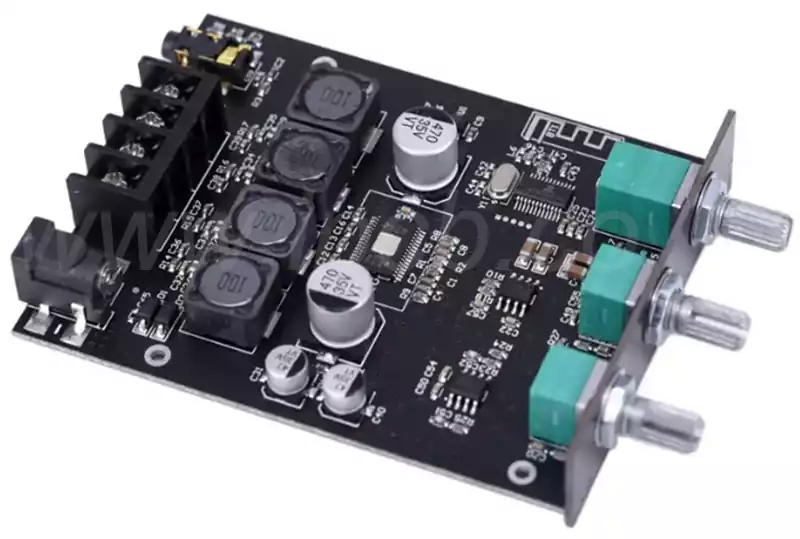
Consumer Electronics
Consumer electronics is the largest market for etched FPCs.
Smartphones and tablets: FPCs are widely used in display connections, camera modules, antennas, and fingerprint sensors. Their flexibility enables higher levels of integration within limited space.
Wearable devices, such as smartwatches, fitness trackers, and AR/VR glasses, require extreme thinness and bendability, making etched FPC an ideal choice.
Foldable screen products: With the rise of foldable phones, the dynamic bending performance of FPC has become critical. The etching process ensures high circuit precision and reliability.
Automotive electronics
As cars transition toward intelligent and electric vehicles, etched FPC plays an increasingly important role. In-vehicle camera and radar modules: These require high-frequency signal transmission, making FPC’s low dielectric loss characteristics ideally suited. In-vehicle central control and display systems: Large-scale flexible circuits can effectively reduce wiring complexity and improve system stability. Power batteries and sensor systems: FPC helps reduce vehicle weight through lightweight design and maintains reliability in high-temperature environments.
Medical electronics
In the medical field, etchedFPCs offer significant advantages in flexibility and miniaturization. Implantable devices, such as pacemakers and neurostimulators, require circuits with extremely high flexibility and long-term stability.
Wearable health monitoring devices, such as flexible sensors attached to the skin, collect physiological data in real time. Diagnostic equipment, such as endoscopes, require FPCs to provide reliable image and signal transmission.
Medical applications place extremely high demands on FPCs, requiring them to not only meet stringent biocompatibility standards but also ensure reliability and safety in long-term use.
Aerospace
In the aerospace sector, lightweighting and reliability are core requirements.
Satellite communication systems: FPCs’ light weight reduces launch costs while also providing strong radiation resistance. Flight control systems require circuits to remain stable in extreme temperature fluctuations and strong vibrations. Space exploration equipment, such as signal acquisition modules within probes, demands high precision and long life.
The use of etched FPCs not only improves device reliability but also meets the requirements for long-term operation in extreme environments.
Emerging Fields
With technological advancements, etched FPCs are continuously expanding into new applications:
5G and future 6G communication equipment: High-speed, high-frequency transmission places extremely high demands on circuit impedance control and low-loss characteristics, which FPCs perfectly meet.
Internet of Things (IoT): A large number of miniaturized devices require the support of flexible circuits.
New Energy Field: In applications such as flexible solar cell modules and power battery management systems, FPCs play a role in energy conversion and transmission.
Development Trends
The future development of etched FPCs can be predicted from the following perspectives:
Higher-Precision Circuit Processing: With the advancement of microelectronics, FPCs will move towards narrower line widths and finer line spacing, potentially reaching 10μm or even lower.
New Material Applications: Ultra-thin PI, liquid crystal polymers (LCP), and high-frequency, low-loss materials will gradually become popular.
Green Manufacturing: As environmental regulations become stricter, processes will increasingly use environmentally friendly etching solutions and recyclable processes.
Three-Dimensional Structures and System Integration: Flexible circuits and modules will be combined to form “flexible electronic systems,” achieving a higher level of integration. Improved Reliability: Continuous optimization is being conducted in dynamic flex life and high-temperature resistance to meet future application requirements.
As can be seen, etched FPCs have become a key component supporting the modern electronics industry and will play an even more important role in future high-end technologies.
Quality Control and Inspection of the Manufacturing Process
The etched FPC manufacturing process involves multiple steps, including etching, lamination, drilling, electroplating, and surface treatment. Defects in any one step can render the entire batch of products scrapped. Therefore, quality control and inspection are crucial throughout the entire production process.
Raw Material Quality Control
Substrates (PI film, copper foil): Must possess excellent thickness uniformity and mechanical strength. The surface roughness of the copper foil directly affects etching accuracy.
Adhesives and cover films: Must be resistant to high temperatures and chemical corrosion, and maintain adhesion after repeated bending.
Chemical Solutions: The concentration, purity, and stability of the etching solution directly impact the etching rate and uniformity.
Strict incoming material inspection is a prerequisite for ensuring the stability of subsequent processes.
Etching Process Control
Etching is a core process in etched FPC manufacturing. Common problems include undercutting, overetching, and residual copper. To ensure quality, the following are required:
Temperature and flow rate control: Maintaining stable etching solution temperature and flow rate to avoid regional rate variations;
Real-time copper thickness monitoring: Etching depth is controlled through an online inspection system to ensure circuit integrity;
Pattern compensation design: Incorporating process compensation into the design phase reduces the impact of undercutting on precision.
Lamination and alignment accuracy
For multi-layer etched FPCs, interlayer alignment and lamination processes are crucial. Lamination temperature and pressure must be uniformly distributed to avoid bubbles and delamination. The alignment system must maintain micron-level accuracy, otherwise, circuit misalignment can occur.
This step typically relies on automated alignment and optical inspection equipment to ensure consistency.
Surface treatment and reliability control
FPC surfaces typically require surface treatment (such as ENIG, OSP, or immersion tin) to ensure solderability and oxidation resistance. Quality control focuses include: uniformity of plating thickness to avoid cracking or poor solder joint contact; and surface cleanliness: residual impurities can seriously affect soldering reliability.
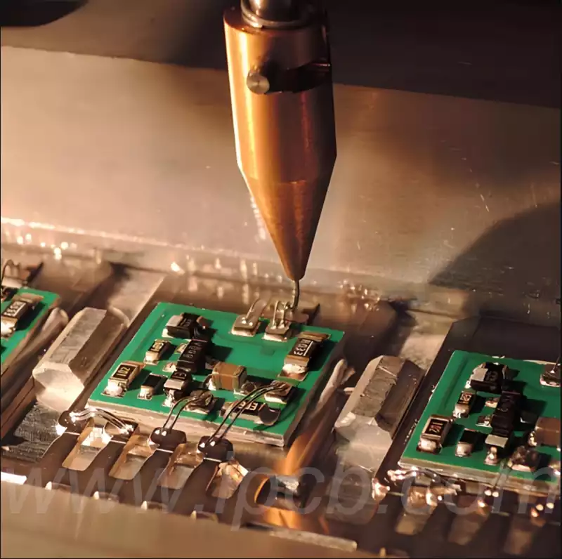
In-Line Inspection and Electrical Testing
Before shipping, finished products must undergo a series of rigorous inspections: Automated Optical Inspection (AOI) to detect circuit defects, shorts, and opens; flying probe testing or electrical testing to verify the connectivity and electrical performance of each circuit; and microstructural analysis: cross-section observation to confirm etching uniformity and copper thickness consistency.
Reliability and Environmental Testing
To ensure the long-term stability of etched FPCs in practical applications, environmental and reliability testing is essential:
Thermal Cycle Testing: Simulates alternating high and low temperature environments;
Flex Life Testing: Verifies performance stability after thousands of flex cycles;
High Humidity and High Temperature Testing: Examines reliability in harsh environments;
Salt Spray Testing: Evaluates corrosion resistance, particularly in automotive and aerospace applications.
Trends in Intelligent Quality Control
With the development of Industry 4.0, etched FPC manufacturing is gradually incorporating intelligent quality control:
Big data monitoring: real-time collection of process parameters to predict potential defects; AI defect detection: leveraging machine vision and deep learning to quickly identify flaws; and closed-loop control systems: automatically adjusting etching solution concentration and temperature to achieve stable production.
This trend not only improves yield but also reduces the cost and risk of manual inspection.
Summary
Etched FPC is an indispensable key technology in modern electronics manufacturing. It combines flexible materials with high-precision conductors to form complex circuit patterns through a precise etching process. This article systematically analyzes the entire etched FPC process and its key elements, covering process principles, material selection, design considerations, technical challenges, application areas, and quality control and inspection.
Several key conclusions can be drawn:
Process precision is fundamental: The uniformity and accuracy of the etching process directly determine circuit quality and reliability.
Material selection is crucial: The matching performance of substrate, copper foil, adhesive, and coverlay is a prerequisite for achieving high-performance flexible circuits.
Design requires comprehensive considerations: Mechanical flexibility, electrical performance, environmental adaptability, and process capability must all be balanced.
Wide applications and promising prospects: From consumer electronics to medical, automotive, and aerospace, etched FPCs provide irreplaceable support for high-end electronic systems.
Quality control and testing are essential: Strict process monitoring, in-line testing, and reliability testing are key to ensuring long-term, stable product operation.
As the demand for thinner, lighter, higher-density, and higher-performance electronic products continues to increase, etched FPC technology continues to advance and will play an even more crucial role in future high-end electronic applications. It is not only the foundation of flexible electronics but also a vital driving force for innovation and development in the electronics industry.