In the fields of mechanical processing, PCB design and product assembly, the design of holes is far more than just a round hole. Different types of hole structures have a direct impact on assembly accuracy, mechanical properties and even product appearance. Counterbore vs countersink are the two most common finishing hole types. Many technicians, purchasers, and even new engineers often confuse the two in actual projects, which affects product quality and even causes rework.
This article will elaborate on the definitions, structural differences, application scenarios, design points and precautions in the manufacturing process of the two, to help readers establish a clear cognitive system and make accurate choices in project practice.
Definition and structural differences
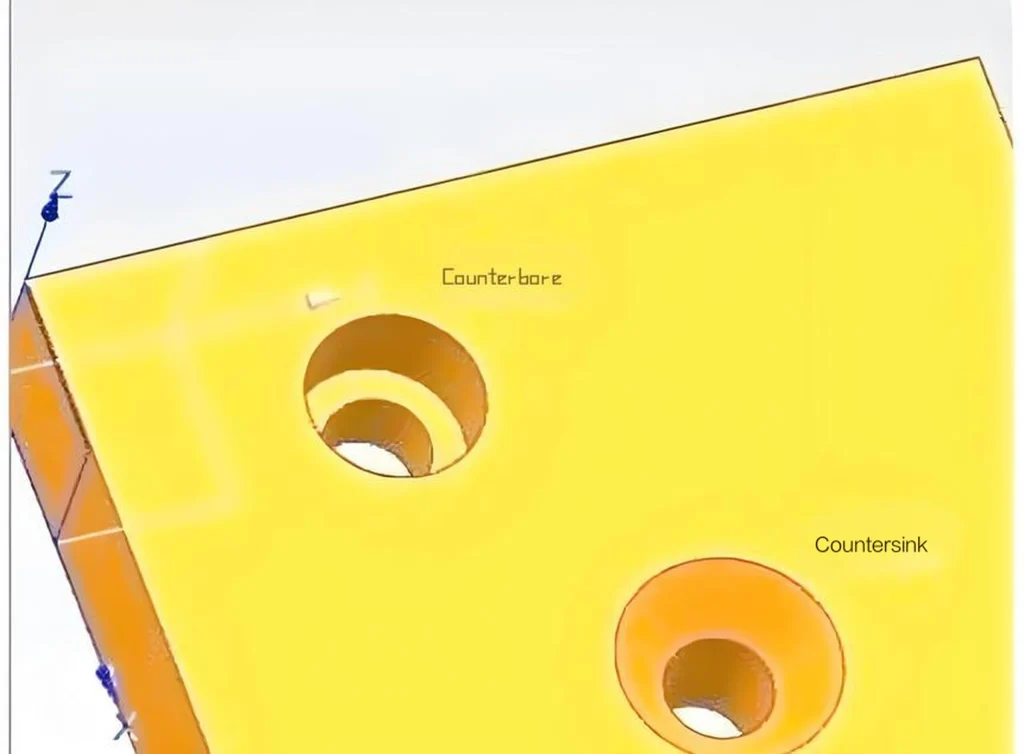
Counterbore is a structure that expands the hole on the upper part of the round hole, usually forming a flat step to accommodate screw heads, bolts or other fasteners, so that they are flush with the surface or slightly lower after installation.
Countersink is a conical bevel machined at the hole mouth, which is usually used for countersink screws, so that the screw head can be embedded below the surface of the workpiece to achieve a non-protruding and smooth installation effect.
The key differences between the two are as follows:
Bottom shape: Counterbore is flat bottom, Countersink is conical bottom;
Screw adaptability: Counterbore is suitable for cylindrical head, hexagonal screws, etc., Countersink is suitable for countersink screws;
Processing tools: The required tool shapes are different, and the processing parameters and sequence are also different;
Visual and structural effects: The former is more structurally fixed, while the latter is more aesthetically pleasing and drag-reducing design.
This difference is not only reflected in mechanical processing, but also extends to PCB screw hole design. For example, some connectors or metal shell assemblies have extremely high requirements for hole type accuracy and interference fit. Wrong selection often leads to unstable structure or poor grounding.
Application scenarios and industry distribution
Different hole type designs correspond to different practical applications. In the product development and mass manufacturing stages, understanding their typical application areas will help avoid rework and cost increases caused by design deviations in the early stages.
Common applications of counterbore:
Fixed connectors in mechanical structures (such as motor mounting holes)
Connection between PCB reinforcement plate and metal housing
Screw fixing points for automobile and aviation parts
3D printing and plastic mold structure assembly
Common applications of countersink:
Housing design with smooth transition surface
Electronic equipment where screws are not allowed to protrude from the surface (such as mobile phone housing)
Mechanical design related to fluid mechanics (avoid wind resistance caused by screw protrusion)
External structure of precision instruments to improve aesthetics
In foreign trade procurement scenarios, special attention should be paid to the terminology used by European and American customers for these two hole types. For example, there are differences in the symbols and dimension markings of these two hole types in ISO standards and ANSI standards. If they are not clear in communication, misunderstandings are likely to occur.
Detailed explanation of countersink: structure, processing and application scenarios
After understanding the basic definitions of countersink and counterbore, it is particularly important to deeply analyze their respective structural characteristics, processing methods and practical application backgrounds. This section will focus on countersink, comprehensively analyze its technical details and application logic, and help readers understand its advantages and limitations from the two dimensions of design and manufacturing.
Structural features of countersink holes
A countersink hole is a conical hole designed to make the screw head flush with the workpiece surface or even slightly lower than the surface. Common angles include 82°, 90° and 100°, among which 90° is the most commonly used industrial standard angle. Structurally, a countersink hole usually includes the following key parts:
Entrance cone: opened according to the geometric angle of the matching screw head;
Through hole area: penetrates the entire workpiece thickness so that the screw can pass smoothly;
Cone angle size control: must strictly match the screw specifications, otherwise it will result in poor assembly strength or poor appearance.
This design effectively reduces the interference of the protruding part on the structural integrity of the product, and is particularly suitable for applications that require a smooth and beautiful surface.
Processing methods and control points
The processing of countersink holes can usually be completed by a special countersink bit or CNC machine tools. The following points should be paid special attention to during the processing:
Drill bit selection and matching: a countersunk drill with the same angle as the target screw head should be selected;
Control hole depth and angle: Too deep will cause the screw to sink too much, affecting the stability of the structure; too shallow will expose the screw and lose the countersunk effect;
Edge burr treatment: a good hole edge deburring process helps to improve the assembly quality;
Repeat accuracy control: in batch processing, consistency needs to be ensured, otherwise it will seriously affect the assembly efficiency.
Modern CNC machining centers are often equipped with automatic countersunk drilling functions, which can efficiently complete repeated hole opening operations in multiple holes and are widely used in high-precision industries such as aviation, electronics and precision instrument manufacturing.
Application fields and design advantages
Countersunk holes are widely used in product designs that require smooth surfaces or invisible screw heads after assembly. Common fields include:
Consumer electronics: such as hidden screw design of laptop and smartphone shells;
Aerospace: hidden screw assembly of fuselage parts that are extremely sensitive to airflow resistance;
Mold manufacturing: dual requirements for appearance and positioning accuracy during mold assembly;
Precision machinery: ensure that parts are tightened without affecting the operating space of the equipment.
Its biggest advantage is that it provides a connection method that combines structural stability and aesthetics, which is particularly suitable for scenarios with high requirements for industrial design.
Potential limitations and risks of misuse
Although countersinks have many advantages, they may also cause problems when used improperly:
Weakened mechanical properties: Since the countersink design weakens the thickness of part of the workpiece, excessive force or insufficient material strength may cause structural damage;
Increased installation difficulty: The hole depth and angle need to be precisely controlled, otherwise mismatching is likely to occur during assembly;
Later maintenance is complex: The screw head is hidden in the hole and is not easy to observe and operate during disassembly.
Therefore, in actual applications, it is necessary to fully verify the design drawings, and rely on experienced engineers to arrange the hole position and control the depth to avoid product quality risks caused by misuse of countersinks.
Detailed explanation of the application scenarios of the two
In engineering practice, Counterbore and Countersink often play a vital role under different assembly requirements. Understanding their significance in different scenarios will help make more efficient and economical decisions in the early stages of product design.
Typical Applications of Counterbore
Embedding countersunk bolts in mechanical assembly
In mechanical designs that require the fixing of heavy-duty parts, such as motor brackets, gearbox housings, or large gear systems, Counterbore is used to allow the head of the countersunk bolt to be completely embedded in the part without protruding from the surface, thereby ensuring that other parts can fit on its surface without interference.
Maintaining bolt head stability
For connections that are subject to high shear or vibration loads, such as brackets for automated equipment or heavy structural steel connections, the flat-bottomed holes formed by Counterbore can provide a good contact surface, making it difficult for the bolt head to slide, and improving long-term assembly stability.
Scenarios requiring secondary positioning or cover installation
In structures such as PCB housings and control panels that require cover or secondary parts installation, Counterbore helps provide a predictable position for the embedding and fixing of screw or nut heads.
Typical Applications of Countersink
Designs that pursue surface flatness
In products with high appearance requirements such as consumer electronics, automotive interiors, and aviation panels, using Countersinks can make the screw head flush with the housing surface, improving the overall aesthetics and reducing user discomfort when touching.
Demand for simplified assembly and maintenance
Since the inclined surface structure can easily guide the screw into the predetermined position, Countersink is particularly suitable for manual or semi-automatic assembly processes, improving efficiency in the mass production stage.
Supporting structure for weight-sensitive design
For the connection of drones, model aircraft or other lightweight components, Countersink screw heads are smaller and lighter, which helps to reduce the overall weight of the design.
Some examples of boundary applications and misuse
Although the two have their own functional characteristics, there are also cases of misuse in actual applications. For example:
Using Countersink for high-strength connections: This type of design may loosen or detach the screw head after long-term use due to the small contact area of the cone.
Using Counterbore but not controlling the flat bottom size: It will cause the bolt head to not be fully embedded, but affect the structural fit or cause interference in dynamics.
Therefore, accurately understanding the purpose of use and the function of the parts is an important part of avoiding design errors.
Processing methods and manufacturing considerations
In the field of machining, hardware assembly or PCB, whether it is a counterbore or a countersink, its design is only the first step. The real challenge is often reflected in the processing process. A reasonable manufacturing process can not only improve product quality, but also reduce costs and rework rate. This section will focus on the processing methods, required tools, common problems and manufacturing considerations of these two hole types to help readers understand the differences between these two design forms more comprehensively from a practical application perspective.
Overview of processing methods
Counterbore processing:
The purpose of countersinking is to process a flat-bottomed circular groove perpendicular to the axis of the hole on the basis of the original through hole or screw hole to accommodate the head of a cylindrical head screw or hexagonal screw. Its processing process is relatively direct, especially on CNC machine tools or drilling machines. It can be completed quickly. The common process steps are as follows:
First drill a pilot hole (consistent with the main rod diameter of the screw);
Replace the countersink drill or use a compound drill bit for flat bottom expansion;
Finally, confirm whether the hole depth is consistent with the thickness of the screw head to ensure that the screw head is flush with the material surface.
Countersink processing:
Countersink is to chamfer the hole mouth to form a tapered groove that matches the tapered screw head. Although the processing process is simple, it has extremely high requirements for angle and centering, otherwise it will cause the screw head to deviate or tilt during assembly. The process steps usually include:
Drilling the screw guide hole;
Using a countersink drill (commonly 82°, 90° or 100° cone angle) for chamfering;
Visually check or use a depth gauge to confirm whether the angle depth is accurate.
Tools and equipment used for processing
Common tools for countersinking:
Counterbore Cutter: With a guide column to ensure alignment with the center of the original hole;
End Mill: Suitable for CNC milling machines for batch processing;
Drill + Counterbore Combo Tool: Save tool change time;
Boring tool: When the hole diameter accuracy is high, a CNC boring tool can be used for fine finishing.
Common tools for countersink holes:
Countersink Cutter: Select according to the angle of the screw used, common angles are 82° (US) and 90° (metric);
Handheld electric drill or CNC drilling machine: used for simple chamfering or mass production;
Deburring tool: used to trim the chamfered edge and improve the finish;
Laser positioning equipment (such as automatic centering):Ensure that the countersink hole is centered and symmetrical.
Common processing problems and solutions
Eccentricity or deflection during countersink processing
Possible reasons: The drill bit is not properly aligned or the guide column is loose;
Solution: Use a countersink cutter with a guide column and check the machine tool spindle runout regularly.
Countersink chamfers with too many burrs
Possible reasons: The tool is not sharp or the feed speed is too fast;
Solution: Replace with a sharp countersink drill, reduce the feed speed and deburr.
Hole depth is too shallow or too deep
Possible reasons: The program setting is wrong or the workpiece is not fixed firmly;
Solution: Use a depth gauge to confirm repeatedly and check the stability of the fixture.
The bottom of the hole is rough or uneven (mostly seen in countersinks)
Possible reasons: tool wear, insufficient cutting fluid;
Solution: Replace the tool regularly to ensure sufficient supply of cutting fluid.
Special considerations in the PCB industry
In the PCB industry, the application of countersinks and counterbores is usually not as common as in hardware processing, but when it comes to mechanical structure combination (such as metal housing, screw fixing requirements), some high-end PCB designs will also use similar processes. At this time, the following points should be noted:
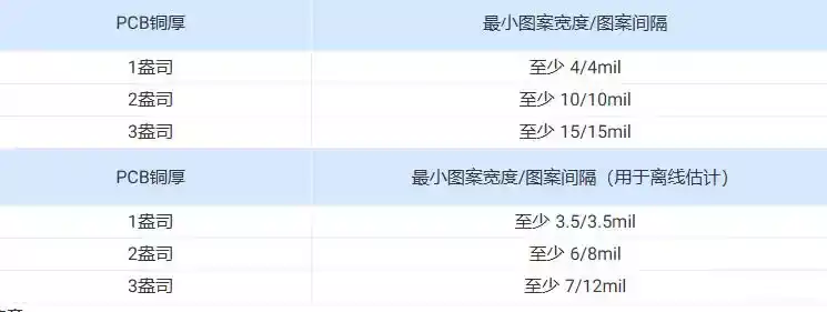
The hardness of the plate is different from that of metal, and it is easy to produce burrs or cracks;
Special PCB milling cutters or laser equipment should be used for chamfering or countersinking;
The processing depth cannot exceed the copper layer or functional area, and it needs to be designed and confirmed in advance;
If there is a screw fixing function, copper ring protection should be designed at the countersink or countersink position.
Selection suggestions in practical applications
When choosing countersinks and counterbores, factors such as the actual application of the product, mechanical structure requirements, processing costs and long-term maintenance must be comprehensively considered. For different industries and working conditions, reasonable hole type selection can not only optimize the assembly quality, but also improve the reliability and service life of the whole machine. The following is a systematic analysis and suggestions from several dimensions:
Assembly goals determine the selection direction
Scenarios where the screws need to be flush with the surface: such as consumer electronics, instrumentation equipment or precision machinery, often require beautiful surfaces or avoid protruding screws interfering with the shell. In this case, countersunk holes should be preferred.
Situations where it is necessary to ensure that the screw head is fully embedded, not exposed, and the structure is tight: such as motor brackets, mold fasteners, and load-bearing structure connections. It is usually recommended to use stepped holes to improve the connection strength and shear resistance.
Consideration of force direction and structural rigidity
Countersunk holes are used for tapered screws. Their structural characteristics make it easy to provide good positioning in the vertical direction, but there is a risk of displacement or loosening when the lateral load is large, especially in a vibration environment.
The cylindrical fit of the stepped hole can better withstand multi-directional load impacts, especially in situations where dynamic load response is required, and the performance is more stable.
Material processing characteristics limitations
Some materials such as aluminum, plastic or composite materials are extremely sensitive to tool angles during processing. The cone angle of the countersunk hole must be matched accurately, otherwise it will cause local overcutting or failure to fit. The step hole is relatively more tolerant in processing, suitable for hard or brittle materials, and reduces the scrap rate.
Convenience of maintenance and replacement
The design of the countersunk hole is prone to problems such as slipping and countersunk breakage if the torque is not controlled during the disassembly process, especially when the screw is repeatedly tightened.
The step hole structure is more stable, the screw head is more protective, and it is easy to observe and handle during maintenance. It is more suitable for equipment with long service life and long maintenance cycle.
Comprehensive cost Analysis
Processing difficulty: Countersinks require precise control of angles and depths, and processing equipment and tool precision requirements are higher, and the unit price is slightly more expensive.
Overall assembly efficiency: Step holes are highly standardized and compatible with a wide range of screws, which is conducive to rapid batch assembly.
Design flexibility: In customized products, countersinks can optimize space utilization, while step holes have fewer design restrictions and are easier to adapt to standard parts.
Summary
In industrial fields such as precision machining, mechanical design, and PCB, countersinks and counterbores are not interchangeable design details, but core choices related to function, safety, and assembly efficiency. Although they seem to differ only in hole structure, they actually represent in-depth considerations of multiple factors such as connection strength, screw type, force direction, and appearance.
Correctly understanding and rationally using these two hole types will not only help improve the assembly quality and overall performance between components, but also reduce rework and loss in procurement, production, and testing, saving costs and improving efficiency. For foreign trade purchasers, being familiar with the English expressions and technical requirements of these two can also help them communicate needs with customers more accurately and evaluate suppliers’ delivery capabilities.
Whether you are an engineer, product manager, foreign trade salesperson or a novice in the industry, mastering this kind of detailed knowledge is not only a reflection of professionalism, but also an effective way to enhance personal competitiveness and optimize project results.