Characteristic impedance, also known as features impedance, is the pure resistance of a circuit or transmission line per unit length when the frequency tends to infinity. It is an inherent characteristic of the transmission line and is not affected by factors such as the frequency, amplitude and phase of the signal. Usually expressed by the symbol Z0, the unit is ohm (Ω).
It reflects the hindering effect of the transmission line on signal transmission and determines the transmission characteristics and matching performance of the signal on the transmission line. When the output impedance of the signal source is equal to the characteristic impedance of the transmission line, maximum power transmission and minimum reflection can be achieved. Therefore, when designing circuits and transmission lines, it is required that the impedances of the signal source, transmission line and load can be matched to minimise signal reflection and loss.
The process of calculating characteristic impedance generally includes the following steps:
1.Define the parameters of the transmission line
Firstly, the parameters of the transmission line should be defined, such as the inductance per unit length (L), capacitance (C) and the length of the transmission line (l) and other indicators.
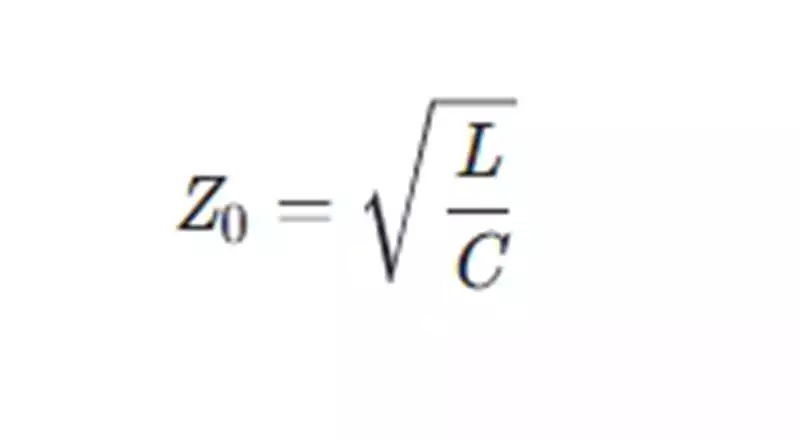
2.Perform characteristic impedance calculation
The characteristic impedance (Z0) can be calculated by the formula:
- Consider the conductivity factor
When conductance (G) exists in the transmission line, the calculation will be adjusted and the formula becomes:
Where R denotes the resistance and ω is the angular frequency.
4.Practical Design Application
In practical engineering, the characteristic impedance is usually determined according to the specific structure (e.g. coaxial cable, microstrip line, double parallel line, etc.) and material properties of the transmission line. The use of these formulas can help engineers in the design and analysis of high-frequency signal transmission lines, to achieve better signal transmission results.
A word of caution:
The inductance, capacitance, resistance and conductance parameters of the transmission line must be used accurately in the calculations.
In transmission line design, it is very important to keep the characteristic impedance matching, which can effectively reduce the signal reflection and attenuation, and thus improve the overall performance of the system.
Difference between characteristic impedance and impedance.
Characteristic impedance and impedance, although similar in name, represent different concepts. Characteristic impedance refers to the unit length of the transmission line in the frequency tends to infinity when the performance of the pure resistance value, is the inherent characteristics of the transmission line, and with the frequency, amplitude and phase of the signal is not related. Impedance is the circuit or component of the overall obstruction of the AC signal, composed of resistance, inductance and capacitance, including real and imaginary parts, the real part reflects the resistance of the signal through the nature of the impediment, the imaginary part of the signal to reflect the phase change.
The difference between the two is also reflected in the description of the object: characteristic impedance for the unit length of the transmission line or circuit, describing the behaviour of the transmission line itself, independent of external connections; while the impedance describes the entire circuit or device on the signal impedance, covering the characteristic impedance of the transmission line as well as its connection with other devices to form a comprehensive impedance. Characteristic impedance is generally an intrinsic value under ideal conditions, while impedance changes with actual conditions such as frequency, amplitude and phase.
In summary, characteristic impedance is a property of the transmission line itself, used to describe the propagation characteristics of the signal within the transmission line, independent of the external connection; impedance is the overall circuit or device on the signal obstruction performance, involving the transmission line and external components. Both of them have different responsibilities in circuit design and signal transmission, and need to be considered comprehensively when designing to meet the actual application requirements.