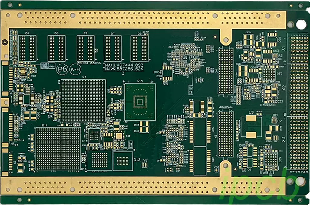
Printed circuit board warpage refers to the phenomenon of PCB board bending, twisting or deformation during the working process. This warpage is usually caused by uneven heat distribution inside the circuit board. Warpage is the degree of bending of the PCB surface in different areas, and this performance parameter is very important in PCB design and manufacturing because it directly affects the reliability, performance and adaptability of the PWB board.
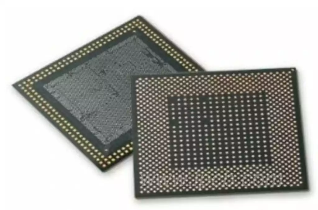
The root cause of warpage problems stems primarily from a mismatch in the coefficient of thermal expansion (CTE) between the BGA and each package component material in the PCB, such as the substrate, wafer, and EMC package material. During placement and movement, the rate of temperature rise affects the uniform temperature distribution across the component, so there is an indirect relationship between the rate of temperature rise and the degree of warpage.
In the case of circuit boards, the larger the package size, the greater the potential for warpage. In addition, differences in rework heating methods (e.g., hot-air rework systems, infrared heating, hot-air reflow ovens, vapor-phase ovens, etc.) can also affect the degree of warpage. Using low CTE thermally conductive materials, the CTE can be customized to partially or completely address this issue.
Some ball grid arrays (PBGAs) with plastic enclosures contain heat sinks, which cause the top of the BGA package to expand more quickly than the bottom; this plastic expansion pulls downward on the corners of the BGA.Moisture in the BGA can also lead to warpage because the component must diffuse in the center. In these cases, the corners of the BGA may curl upward.
Through a series of experimental designs, it is possible to determine which part (BGA or PCB) is undergoing warpage. Conducting experiments that isolate the push-pull surfaces can help determine how to address this issue.

To minimize warpage, when a BGA is bent, its corners will experience maximum displacement, which may result in a large number of opens and bridges. Similarly, the board may bend upward or downward, pushing the solder paste inward and causing bridging or open circuits. These problems should be detected by visual inspection or X-ray.
One way to minimize warpage is to slow down the heating and cooling process. During preheating, the temperature gradually increases; during cooling, the temperature gradually decreases. However, during the cooling process, the temperature should not drop too slowly to avoid the formation of rough microstructures. In electronics manufacturing, a proper balance needs to be found between the two.
Controlling moisture sensitive devices (MSDs), including printed circuit boards and assemblies, is another way to minimize the effects of warpage.J-STD-0033 and the JEDEC Humidity Handling Guidelines are the best reference guides for proper handling of MSDs. If their warpage is related to moisture absorption, pre-baking the boards and assemblies and keeping them dry in a dry environment can mitigate warpage issues. Limiting exposure time and knowing the MSD rating of boards and assemblies will also play an important role in reducing warpage associated with moisture absorption.
The pillow effect can be minimized by using a solder paste that meets a specific formula and combining it with the proper solder paste, which can also limit the effects of solder ball warpage.
By properly designing the volume of solder paste applied at each pad location, some of the problems associated with PCB and device warpage can be effectively limited. In some cases, the pads shift during the printing process, while in other cases, the volume of solder paste on the pads decreases during the printing process, which can compensate for the effects of warpage.