Introduction – The Importance of Flex Assembly and Industry Background
As electronic products continue to evolve towards thinner, more compact, and higher-performance designs, traditional rigid PCBs are no longer able to meet the demands of some specialized applications. Therefore, flexible assembly has become an indispensable component of modern electronics manufacturing. It not only provides flexibility in space utilization but also withstands certain mechanical flexures and dynamic stresses, thereby providing greater freedom in product design.
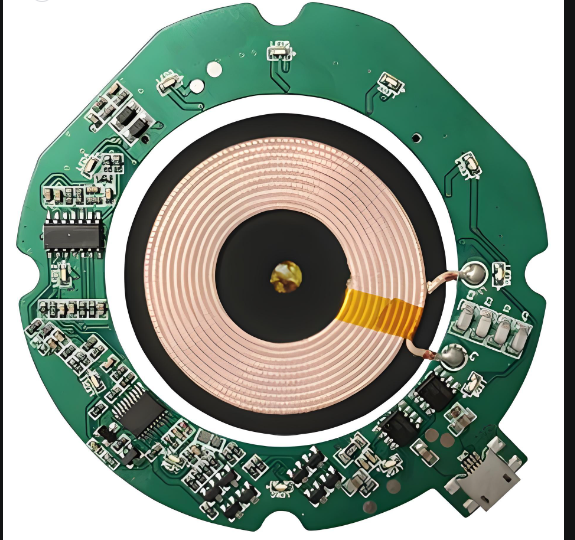
In the consumer electronics sector, smartphones, tablets, and wearable devices commonly use flex assembly to achieve complex internal connections and multi-layer layouts. With the introduction of flexible circuit boards, designers can integrate signal transmission, power distribution, and sensor interfaces within limited space, reducing device size and weight while ensuring stable performance.
Flex assembly also plays a vital role in the medical electronics and industrial control fields. For example, portable medical monitoring devices require flexible circuits to connect multiple sensors while ensuring long-term wear comfort. Industrial automation equipment requires high-density circuitry within limited space and withstand mechanical vibration and temperature fluctuations. Compared to traditional rigid PCBs, flex assembly can achieve complex layouts and dynamic flexure without compromising reliability.
Furthermore, the automotive and aerospace electronics industries place extremely high demands on reliability and durability. Flex assembly, with its lightweight, flexible, and foldable properties, enables high-speed signal transmission and power system connections even in confined spaces. Flexible assembly holds significant potential, particularly in future new energy vehicles, unmanned systems, and aerospace control systems.
From a market perspective, the global flex assembly market has shown rapid growth in recent years. According to industry data, the compound annual growth rate is projected to exceed 8% over the next five years, primarily driven by continued demand for consumer electronics, medical devices, and automotive electronics. Simultaneously, advances in manufacturing processes and materials science are continuously driving performance improvements in flex assembly, further strengthening its advantages in high-density, high-speed, and high-reliability applications.
In summary, flex assembly is not only a technological innovation in electronics manufacturing but also a crucial tool for electronic product design and performance improvement. Understanding its basic concepts, material properties, and application scenarios is essential knowledge for technicians, procurement personnel, and newcomers to the industry, and forms the foundation for the in-depth analysis that follows in this article.
Basic Concepts and Classifications of Flex Assembly
Basic Concepts of Flex Assembly
Flexible assembly refers to an assembly technology that utilizes flexible printed circuits (FPCs) or flexible materials for routing, soldering, and connecting electronic components. Unlike traditional rigid PCBs, the key features of flex assembly lie in its bendability, foldability, and thinness, while maintaining electrical performance and mechanical reliability within confined spaces.
Flex assembly encompasses not only flexible circuit board wiring but also a complete process, including component placement, soldering, wire routing, shielding, and protective coating. Therefore, it plays a central role in the miniaturized, high-density design of modern electronic products.
Compared to traditional PCBs, flex assembly offers the following advantages:
High space efficiency: Foldable and bendable, it allows for complex circuit connections within limited spaces.
Lightweight: Flexible substrates are thinner and lighter than rigid boards, helping to reduce overall device weight.
Dynamic adaptability: Able to withstand a range of mechanical flex and vibration, it is suitable for wearable devices or dynamic applications.
High reliability: Under strict design and manufacturing controls, it can achieve high-speed signal transmission and long life.
Flex assembly classification
Flex assembly can be categorized in multiple ways based on structural form, application function, and process characteristics.
Classification by Structural Form
Single-Sided Flex Assembly (SSA) places the circuitry on only one side of the flexible substrate. It is suitable for products with low signal throughput and simple wiring.
Advantages: Low manufacturing cost and simple design.
Applications: Basic sensor modules and simple interface connections.
Double-Sided Flex Assembly (DSA) places the circuitry on both sides of the flexible substrate, connected via vias or buried vias.
Advantages: Increases wiring density and saves space.
Applications: Complex internal wiring in smart wearable devices and small instruments.
Multi-Layer Flex Assembly (MLA) forms multi-layer flexible circuits through bonding or lamination, supporting high-density signal transmission.
Advantages: Meets the requirements of high-speed signals and complex power networks.
Applications: High-end mobile phone motherboards, aerospace control boards, and medical imaging equipment.
Classification by Application Function
Signal transmission type: Primarily used for high-speed data transmission, requiring precise impedance matching and good signal integrity.
Power transmission type: Carries high current or high-power signals, requiring thicker copper foil and considering heat dissipation. Hybrid (Signal + Power) assembly combines high-speed signal and power transmission, often used to connect motherboards and sensors or driver modules within complex electronic products.
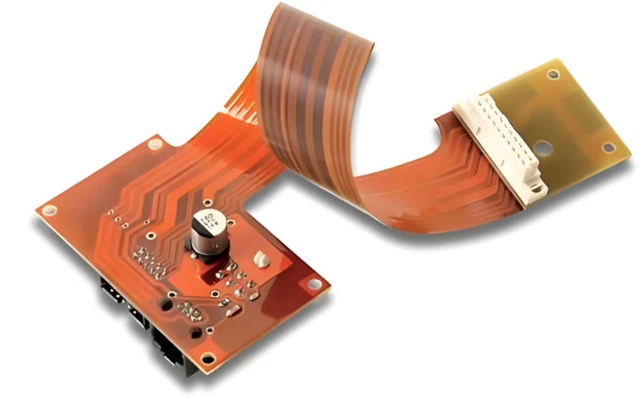
Flex assembly is often combined with rigid PCBs to form a rigid-flex assembly:
The rigid area is used for dense component soldering, while the flexible area is used for connection or folding.
Advantages: It provides both mechanical support and flexible wiring space.
Applications: Multi-layer module connections within smartphones and automotive electronic control units.
Design and Classification Key Points
When selecting and designing a flex assembly, consider the following key points:
Substrate Type: PI, PET, LCP, etc. Different substrates affect flexibility, thermal stability, and signal characteristics.
Copper Foil Thickness: Determines conductivity, power handling, and thermal management.
Bend Radius and Number of Dynamic Bends: Impact lifespan and reliability.
Number of Layers and Via Design: Impact wiring density and signal integrity.
Surface Treatment: Protective layer and solder mask ensure long-term reliability.
By understanding these design key points, engineers can select the most appropriate flex assembly type based on specific product requirements, achieving high-density, lightweight, and reliable electronic connection solutions.
Application of Materials Science in Flex Assembly
In flex assembly, the choice and properties of materials directly determine the performance, reliability, and service life of the circuit board. Understanding the properties of the flexible substrate, conductive layer, protective layer, and adhesive is crucial for the design, manufacture, and maintenance of flex assembly.
The flexible substrate is the core carrier layer of a flex assembly, and its selection influences the circuit board’s flexibility, temperature resistance, mechanical strength, and signal transmission performance. Key substrates include:
Polyimide (PI)
Performance: High-temperature resistance (up to 400°C), high mechanical strength, and low thermal expansion coefficient.
Advantages: Suitable for high-reliability, high-temperature soldering, and dynamic bending applications.
Applications: High-end mobile phone motherboards, aerospace equipment, and automotive electronic control modules.
Polyester film (PET)
Performance: Good flexibility and low cost, but relatively low temperature resistance (approximately 150°C).
Advantages: Suitable for low-cost, lightweight electronic products.
Applications: Wearable devices and basic sensor modules.
Liquid Crystal Polymer (LCP)
Performance: Excellent high-frequency performance, low thermal expansion coefficient, and good chemical stability.
Advantages: Suitable for high-frequency, high-speed signal transmission and microwave applications.
Applications: High-speed communication modules and 5G RF components.
When selecting a substrate, it is important to comprehensively consider operating temperature, bend radius, lifespan requirements, and cost.
The conductive layer is a key layer in flex assembly for signal and power transmission. Its material properties influence electrical conductivity, power handling capacity, and thermal management. Main materials include:
Copper Foil
Common thickness range: 9μm to 70μm; thickness determines maximum current carrying capacity.
Surface treatment: Anti-oxidation coating or gold plating is used to improve soldering performance and long-term reliability.
Features: Excellent conductivity, capable of forming high-density wiring when bonded to the substrate.
Conductive Adhesive Layer
Used in multi-layer flex or rigid-flex boards.
Purpose: Connects the flexible and rigid layers, ensuring mechanical strength and electrical conductivity.
Material selection must balance flexibility and conductive stability. Impedance control must also be considered in the design of the conductive layer. Especially for high-speed signal transmission, the effects of conductor width, copper thickness, insulation thickness, and bending on impedance must be precisely calculated.
Coverlay and Solder Mask are primarily used to prevent mechanical damage, chemical corrosion, and electrical shorts. They also provide solder hole positioning and fluxing during the soldering process.
Coverlay covers the conductive surface of a flexible circuit, leaving only the pads exposed.
Function: Protects the traces and provides mechanical support when the flexible board is bent.
Common materials: Polypropylene (PI) film with pressure-sensitive adhesive (PSA) or liquid PI coating.
Flexible solder mask is used for localized protection and solder joint positioning on flexible circuit boards.
Function: Prevents solder bridging and improves solder joint reliability.
Features: Provides flexibility, heat resistance, and electrical insulation.
Adhesives & Interface Materials
In multi-layer flex or rigid-flex boards, adhesives provide interlayer connections and stress buffering.
Thermosetting adhesives: High-temperature resistant, suitable for high-reliability applications.
Pressure-sensitive adhesives (PSA): Easy to quickly bond, suitable for low-cost or rapid prototyping.
Adhesive selection should consider flexibility, thermal expansion matching, thermal conductivity, and aging characteristics. The right material combination and interface design ensure that the flex assembly maintains electrical performance and mechanical reliability under conditions of bending, vibration, and temperature fluctuations.
Design Principles and Challenges
In flex assembly design, in addition to material selection, proper structural design and stress control are key to ensuring circuit reliability and performance. Improper design can lead to cracked solder joints, broken traces, or signal distortion, so understanding the design principles and challenges is equally important for engineers and procurement personnel.
Bend Radius and Dynamic Stress Design
The bend radius is the minimum allowable bending radius for a flex assembly during use. Generally, a larger bend radius results in more reliable circuit boards; a smaller bend radius can lead to wire breakage or copper foil peeling.
The recommended design formula is: Minimum bend radius ≥ 10 × substrate thickness (a larger safety factor is required for dynamic bending).
Dynamic stress: For wearable or foldable electronic products, flex assemblies must withstand repeated bending and vibration. During design, it’s important to consider material fatigue properties, optimize trace routing (avoid vertical bends), increase buffer zones, and rationally arrange via and pad locations.
High-Density Wiring and Fine-Pitch Layout
With the trend toward miniaturization of electronic products, high-density wiring has become a core challenge in flex assembly design:
Wire width and spacing: Typically less than 100μm, requiring precise exposure and etching processes.
Signal integrity: High-speed signal lines require controlled impedance matching to prevent crosstalk and signal reflections.
Interlayer interference: Multi-layer flex assembly design requires careful attention to the layout of power and signal layers to prevent electromagnetic interference (EMI/EMC) from impacting performance.
Shielding layers, differential line layout, and impedance control techniques can be employed to ensure stable high-speed signal transmission.
Thermal Management and Heat Dissipation Design
Flex assemblies are typically thin, and copper layers have limited thermal conductivity. Long-term operation or high-power circuits can cause localized overheating.
Increasing copper thickness, adding heat-dissipating copper foil, or filling with thermally conductive adhesive can improve thermal conductivity.
For high-frequency signals, the impact of the material’s dielectric constant on signal loss must also be considered. Selecting a substrate with low dielectric loss can minimize signal attenuation.
Pad and Connection Design
Pad size and shape: Pads must match component pins while leaving sufficient solder coverage to ensure solder joint reliability.
Via and through-hole design: Vias in flexible boards require optimized diameter, plating thickness, and placement to prevent cracking during bending.
Rigid-Flex design: In rigid-flex boards, the transition between the rigid and flexible areas must be smooth to avoid stress concentration that can lead to fracture.
Reliability Design Challenges
Mechanical fatigue: Repeated bending can cause wire breakage or delamination, requiring both material and wiring design to mitigate risk.
Environmental stress: Temperature fluctuations, humidity, and chemical corrosion can all affect performance, requiring material selection and protective layer design to mitigate risk.
Manufacturing tolerances: Fine-pitch wiring and multi-layer build-up boards require high process precision, making tolerance control critical to design success.
By properly designing bend radius, wiring layout, thermal management, and pad connections, while also incorporating material properties, engineers can maximize the reliability and service life of flex assemblies.
Manufacturing Process and Quality Control
In flex assemblies, manufacturing processes and quality control directly impact the reliability and performance of the final product. Because flexible materials are susceptible to mechanical stress, thermal stress, and chemical corrosion, every process step requires meticulous management.
Manufacturing Process Overview
The flex assembly manufacturing process can be divided into the following major steps:
Substrate Preparation. Select a suitable flexible substrate (such as PI, PET, or LCP) and cut it to the required size. Surface cleaning is performed to remove dust, grease, and impurities to ensure good adhesion of the copper foil.
Copper Cladding and Adhesive Layer Treatment. The copper foil is secured to the flexible substrate by lamination or adhesive bonding. The lamination process requires controlled temperature and pressure to ensure a tight bond between the copper foil and the substrate to prevent subsequent delamination due to bending.
Photolithography and Exposure. A photoresist film is formed on the copper foil according to the design. High-precision exposure equipment is used to transfer the circuit pattern onto the film, preparing for subsequent etching.
Etching. Chemical solutions are used to remove unwanted copper layers, forming precise circuits. High control of fine-pitch wiring is required, and etching uniformity and edge accuracy are critical.
Drilling and Via Processing. Through-holes or buried vias are drilled into the flexible board according to the design. Copper plating or electroless copper filling of holes ensures the conductivity and mechanical stability of multi-layer connections.
Coverlay and Solder Mask Treatment: Cover the PCB surface with coverlay or flexible solder mask to protect the circuitry and provide solder pads. This step ensures soldering quality and provides mechanical support for the flexible board.
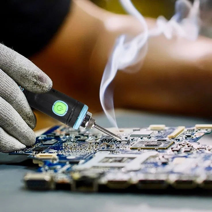
Component Placement and Soldering: Component placement is performed according to the BOM, either manually or automatically. Soldering can be performed using reflow or wave soldering, with a controlled temperature profile to prevent thermal deformation of the flexible substrate.
Inspection and Testing: After PCB production is complete, electrical performance testing, bend testing, and visual inspection are performed. High-speed signal boards also require impedance testing to ensure signal integrity.
Key Quality Control Steps
Material Inspection: Incoming flexible substrates, copper foil, and adhesives are tested for thickness, flexibility, temperature resistance, and chemical stability.
Process Monitoring: Processes such as photolithography, etching, drilling, and copper plating require strict control of temperature, time, and chemical solution concentration to ensure dimensional and continuity accuracy.
Welding Quality Control: Precisely control soldering temperature, solder volume, and time to prevent cold joints, solder bridges, and pad delamination.
Reliability Testing
Bend Testing: Simulates the number and radius of bends experienced in actual use to ensure circuit durability.
Thermal Cycle Testing: Tests the performance stability of materials and solder joints under high and low temperature fluctuations.
Vibration and Shock Testing: Evaluates the impact of mechanical stress on solder joints and flexible circuits.
Defect Analysis and Correction: Analyzes the causes of detected circuit opens, shorts, copper foil peeling, or coverlay defects. Improves process parameters or material selection to avoid recurrence.
Manufacturing and Design Collaboration
Manufacturing processes are closely linked to design principles:
Design parameters such as bend radius, trace width, and via layout must be strictly adhered to during production.
Multi-layer flex assembly and Rigid-Flex boards require higher precision in press-fitting, drilling, and copper plating.
The manufacturing team must collaborate with design engineers to optimize the design to meet actual process capabilities and ensure final product reliability.
Through strict control of every manufacturing step and meticulous quality inspection, flex assembly can achieve optimal performance in high-density, high-speed, and high-reliability applications.
Application Scenarios
Flex assembly, with its lightweight, bendable, and high wiring density, has penetrated multiple high-end electronic applications. Different industries have varying requirements for its design, materials, and manufacturing processes, which is one of the reasons for the continuous evolution of flex assembly technology.
Consumer Electronics. Flex assembly is widely used in consumer electronics such as smartphones, tablets, and smartwatches.
High Space Utilization: Flex connections between mobile phone camera modules and motherboards enable more compact internal structures.
Thinness and Lightness: Flex assembly can replace multiple cables, reduce connector usage, and reduce weight and thickness.
Stable Signal Transmission: Flex assembly ensures low-loss transmission of high-speed signals when connecting high-pixel cameras, OLED screens, and motherboards.
Medical Devices
Medical electronic equipment places extremely high demands on reliability, safety, and durability.
Flexibility and Chemical Resistance: Flex assembly used in medical probes, wearable monitoring devices, and implantable sensors must withstand repeated bending and corrosion from disinfectants. Miniaturization and High-Density Wiring: In portable devices such as ECG monitors and blood glucose meters, flexible circuits can significantly reduce product size.
Biocompatibility: Some medical flexible circuits require special coatings to ensure safe contact with the human body.
Automotive Electronics
With the advancement of automotive electronics and intelligent technology, the use of flex assembly in automotive interiors is rapidly increasing.
High-Temperature and Vibration Resistance: Flex assemblies used in instrument panels, onboard cameras, and radar modules must withstand temperature fluctuations ranging from -40°C to 125°C and long-term vibration.
Complex Space Wiring: Flexible circuits can be arranged along curved surfaces, saving installation space.
High-Speed Signal Transmission: In ADAS (Advanced Driver Assistance Systems) and in-car entertainment systems, flexible circuits enable high-definition video signals and high-speed data transmission.
Aerospace
In the aerospace industry, weight and reliability are top priorities.
Lightweight: Compared to traditional rigid PCBs, flex assembly can reduce weight by up to 60%.
Extreme Environment Resistance: Flex assembly can operate long-term in harsh conditions such as vacuum, radiation, and high-temperature cycling. Shock and vibration resistance: Suitable for high-reliability missions such as satellite communication modules and spacecraft attitude control systems.
Industrial Control and Robotics
The demand for flexible circuits in industrial automation and robotics focuses on dynamic bending and high-speed transmission:
Long dynamic bending life: Connections between robotic arm sensors, camera modules, and main control systems must withstand hundreds of thousands of bending cycles.
Oil and high-temperature resistance: Flexible circuits in industrial environments must withstand oil mist, dust, and high temperatures.
While the application requirements of flex assembly vary across different fields, their core strengths all revolve around lightweight, high reliability, and flexible design. These diverse usage environments are driving continuous advancements in materials, design, and manufacturing processes, laying the foundation for a wider range of future applications.
Maintenance, Testing, and Reliability Assurance
While reliability control during the design and manufacturing stages of flex assembly is crucial, maintenance and testing are equally critical to ensuring long-term stable operation during actual product use. Since flexible circuit boards are often used in dynamic bending, confined spaces, and high-stress environments, scientific testing and reliability assurance directly impact product lifespan and user experience.
Common Failure Modes
During use, flex assemblies may experience the following failures:
Copper foil cracks or fractures: These are caused by repeated bending or excessive stretching, often occurring in areas with a small bend radius or poorly designed areas.
Solder joints with cold or detached solder joints: These are caused by poor soldering procedures or prolonged vibration, leading to fatigue failure of the solder joints.
Coating film peeling: Inadequate adhesion of the coverlay or solder mask can cause short circuits or oxidation of the exposed copper foil.
Via cracking: The difference in expansion coefficient between the copper plating and the substrate during thermal cycling or mechanical shock can lead to cracks.
Environmental aging: Long-term exposure to high temperature, high humidity, or chemically corrosive environments can degrade the performance of flexible materials.
Test Methods
To prevent potential failures, systematic testing should be performed during shipment and application:
Electrical Performance Testing
Open/Short Circuit Testing: Ensures continuity integrity.
Impedance Testing: For high-speed signals, ensures that the circuit meets design specifications.
Power Integrity Testing: Evaluates the stability of the power supply system. Mechanical Performance Testing
Flex Life Test: Verifies the durability of copper foil and circuitry through repeated bending tens of thousands of times.
Vibration Test: Simulates the sustained vibration found in automotive and aviation environments to test solder joint and connection reliability.
Tensile Test: Evaluates the mechanical strength of flexible circuits under tensile loads.
Environmental Adaptability Test
Thermal Cycling Test: Cycles between -40°C and 125°C to assess the effects of thermal expansion.
High Humidity Test: Accelerates aging in high humidity environments to verify oxidation and moisture resistance.
Salt Spray and Chemical Corrosion Test: Particularly suitable for automotive and industrial applications.
Failure Analysis and Improvement
When a flex assembly fails during use, failure analysis is essential:
Physical Cross-Sectioning: Observes the fracture location and changes in the material structure.
Microscopic Examination: Detects cracks, voids, or delamination in the copper foil.
Chemical Analysis: Determines the source of corrosion or material degradation.
Thermomechanical Analysis: Verifies damage caused by thermal expansion coefficient mismatch.
Based on the failure analysis results, targeted optimizations can be made at the design, material, or process levels. For example: adjusting copper thickness in bending areas, adding solder mask, and using high-temperature-resistant adhesives.
Full-Lifecycle Reliability Thinking
Flex assembly reliability assurance shouldn’t be limited to the manufacturing phase; it should be integrated throughout the entire lifecycle: design → manufacturing → testing → use and maintenance.
Prevent problems during the design phase; reduce defects during the manufacturing phase; identify potential hazards during the testing phase; and extend lifespan through maintenance during the use phase.
Only by prioritizing reliability throughout the entire process can flex assembly operate stably and long-term in complex applications and truly realize its value.
Summary
As a vital component of modern electronics manufacturing, flex assembly is continuously expanding its application boundaries thanks to its lightweight, flexible, and high-density wiring. From consumer electronics to healthcare, from automotive electronics to aerospace, it not only solves the challenges of space constraints and dynamic bending, but also provides greater freedom and innovation in product design.
A systematic analysis of its concept, structure, materials, manufacturing processes, application scenarios, and reliability assurance demonstrates that flex assembly is more than just a flexible circuit; it is a complete solution encompassing design, materials, manufacturing, assembly, and testing. It has a direct impact on the performance, reliability, and lifespan of electronic systems.
In the future, with the continued advancement of new materials, new processes, and intelligent manufacturing, flex assembly will continue to evolve towards thinner, lighter, faster, and more environmentally friendly options. Its application value will be further amplified, especially in emerging fields such as wearable healthcare, smart cars, 5G/6G communications, and flexible displays.