Introduction – Why Pay Attention to the Health of Your Aquarite Control Board
In swimming pool water quality management, automated salt chlorination systems are widely adopted for their efficiency, environmental friendliness, and reduced chemical use. The Aquarite Control Board, the “brain” of the entire salt chlorination system, is responsible for monitoring water salinity, controlling the operation of the electrolysis unit, displaying water quality parameters, and issuing alarm signals. A malfunction in this control board can not only result in insufficient or excessive chlorine production, but can also lead to deteriorating water quality, corrosion of pool equipment, and even additional repair costs.
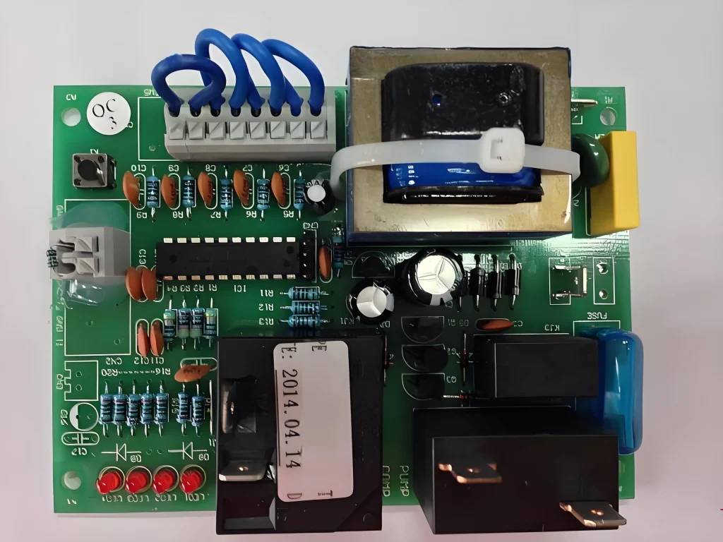
Many pool maintainers, equipment buyers, technical engineers, and even new users often face the question of how to determine if a control board problem exists. In other words, how to tell if your aquarite control board is bad is both a technical and practical question.
Control board malfunctions aren’t always obvious. Sometimes they manifest as an error code on the display, sometimes as abnormal water quality parameters, or sometimes as overall unstable equipment operation. Understanding these potential warning signs and mastering scientific detection methods can help you take action before a malfunction escalates, extending equipment life and reducing maintenance costs.
In this article, we’ll delve into typical Aquarite control board failure signals, detection tools and methods, diagnostic criteria, and preventative measures, as well as professional recommendations for replacement and repair. Whether you’re a technician, a regular customer, a foreign trade buyer, or a newcomer to the industry, you’ll find a comprehensive and actionable reference here.
Core Functions and Working Principles of the Aquarite Control Board
To understand how to tell if your aquarite control board is faulty, you must first understand its role and operational mechanisms in the entire salt chlorination system. The Aquarite control board is the brains of the system, working alongside hardware such as sensors, electrolysis cells, and a display unit to ensure pool water quality remains within safe and comfortable limits.
Main Functions of the Control Board
Salinity Detection and Adjustment
The control board connects to a salt sensor to read the salt concentration in the pool water in real time. If the salinity is low, it prompts you to add salt; if the salinity is too high, it issues a warning to prevent damage to the electrolysis cell.
Chlorine Production Control
Based on water quality requirements and user settings, the control board adjusts the electrolysis unit’s power supply duration and intensity to ensure stable chlorine production, preventing both bacterial growth caused by insufficient chlorine and skin and eye irritation caused by excessive chlorine.
Water Temperature Monitoring
Some Aquarite models feature integrated temperature sensing, which detects water temperature and optimizes electrolysis efficiency based on temperature fluctuations, as water temperature directly affects the salt-chlorination reaction rate.
Error Monitoring and Alarms
When sensor signals are abnormal, power supply fluctuations occur, salt concentration is outside the normal range, or the electrolysis unit is malfunctioning, the control board triggers error codes and alerts the user via the display or indicator lights.
Data Interaction and User Operation
Users can use the buttons, knobs, or digital keypad on the control board to set parameters such as operating mode, chlorine production percentage, and run time, and view real-time operating data.
A Brief Overview of the Control Board’s Working Principle
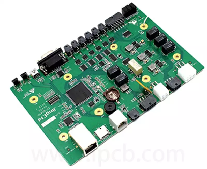
The Aquarite control board primarily consists of a microcontroller (MCU), power module, signal processing circuitry, and a display and user interface. Its operation is broadly divided into the following steps:
Input Signal Acquisition
The control board collects raw signals from salinity sensors, water temperature sensors, current sensors, and other sensors.
Data Processing and Analysis
The MCU amplifies, filters, and digitizes the input signals, then uses a pre-set algorithm to determine water quality and device load requirements.
Output Control
Based on the calculated results, the control board adjusts the operating current and voltage of the electrolysis unit, altering the chlorine production rate.
Status Display and Alarms
Processing results and operating status are displayed to the user via an LCD screen, LEDs, or error codes. If an abnormality is detected, the control board immediately issues an alarm.
Why Understanding the Principle Helps Identify a Fault
Many users tend to attribute problems to the control board itself when determining whether it is damaged. However, some abnormalities may stem from external factors, such as salinity deviation, sensor failure, or electrolysis unit aging. Understanding the workings of the control board can help you more accurately distinguish:
Is there a problem with the control board’s signal processing circuit?
Is the data fed back by the input sensor inaccurate?
Or is the output control unit unable to drive the electrolysis cell?
Only by identifying the source of these problems can you scientifically determine whether the board is faulty, rather than blindly replacing it and incurring unnecessary expenses.
Common Fault Signals and Manifestations of Aquarite Control Boards
To accurately determine whether an Aquarite control board is faulty, you first need to understand the possible signals it may display when operating abnormally. These signals may appear on the display, LED indicators, alarm codes, or changes in operating status.
Abnormal Indicator Lights
Power Light Off
Under normal circumstances, the Power light should remain on after power is applied.
If the Power light is off, it may indicate a faulty power module on the control board, a blown fuse, or damage to the mainboard power supply circuit.
First, check the external power supply and fuses before considering a control board problem.
The Generating Light is off or flashing
This indicates that the control board is not producing chlorine. Possible causes include low salinity, aging of the electrolysis cell, or a faulty output driver on the control board. If the water quality is normal and the electrolysis cell is in good condition, but the light still displays abnormally, it’s most likely due to a malfunction in the control board’s output control circuit.
A continuous light (Check Salt or Inspect Cell) indicates an abnormal salt concentration or electrolysis cell.
If the abnormality persists after adding salt or replacing the electrolysis cell, it’s likely due to a problem with the control board’s signal acquisition and judgment module.
Display Error Codes
Different Aquarite control board models will display error codes on the screen, for example:
Code 91/92: Abnormal salinity detected, possibly due to a sensor failure or control board signal processing error.
Code 120/121: Abnormal water temperature sensor data, possibly due to a damaged sensor or control board input circuitry error.
Code 170/171: Abnormal electrolysis cell output current, often due to a damaged output driver or power control module failure.
These error codes don’t necessarily mean the board is faulty, but if the error persists after troubleshooting external devices and sensors, it’s highly likely a problem with the control board itself.
Abnormal Operation
In addition to lights and codes, the control board’s operating status can also reflect its health:
Significant decrease in chlorine production
If chlorine production is still significantly reduced under normal conditions such as salinity, water temperature, and pH, this may indicate insufficient output power from the control board.
Frequent restarts or freezes
This can occur due to abnormal operation of the power regulator module or MCU within the control board.
Parameters cannot be saved
If all set parameters such as chlorine production and run time are lost after each power outage, the on-board storage module may be damaged.
Why These Signals Are Critical
These visual signals and operational performance are the first step in determining the health of the Aquarite control board. They not only indicate “what’s wrong” but also provide clues for subsequent, more in-depth diagnosis (Section 4), thereby reducing the cost and risk of blind removal and replacement.
Diagnosis by Elimination – Step-by-Step Determination of Control Board Damage
The most effective method for determining whether an Aquarite control board is damaged is a process of elimination. By sequentially checking external conditions, attached equipment, and the internal status of the control board, you can minimize misdiagnosis and unnecessary replacement costs.
Check the external power supply and connections.
Confirm the power input.
Use a multimeter to check whether the voltage at the control board’s power input meets the requirements (usually 120V or 240V AC, depending on region and model).
If the input voltage is insufficient or fluctuates significantly, first address the power supply issue.
Check the fuse.
Open the control board’s housing, locate the main fuse, and check if it is blown.
A blown fuse may be caused by a short circuit, lightning strike, or power surge. If the fuse blows again after replacing it, suspect a fault with the power module inside the control board.
Confirm that the wiring is secure.
Loose terminals or corroded connections can cause power outages or signal abnormalities.
It is recommended to clean and re-tighten the connections after disconnecting the power.
Check peripheral components.
Before suspecting a control board problem, first confirm that the peripheral components (electrolysis unit, sensors, pump, etc.) are functioning properly:
Electrolysis unit: If the unit board is severely scaled, damaged, or has reached the end of its life, this will directly lead to a decrease in chlorine production, similar to the symptoms of a control board failure. Salinity sensor: Abnormal readings may indicate a defective sensor, not a signal processing issue on the control board.
Temperature sensor: Damage can cause the control board to misjudge operating conditions, resulting in chlorine production cessation.
Testing method: Replace these components with a functioning control system or replace suspected components with known functioning components.
Inspect key modules within the control board:
Power conversion module
The control board converts AC power to DC power for the MCU and output drivers.
A damage to the conversion module can cause the entire board to become inoperable or unstable.
Signal processing circuit
Includes the input section that collects information such as salinity, temperature, and current.
If this section is damaged, the control board may erroneously issue an error message.
Output driver section
Converts control signals into high current to drive the electrolysis unit.
Common faults include burnt MOSFETs and damaged relay contacts.
Testing method: If possible, use an oscilloscope or multimeter to test the voltage and waveform of the circuit nodes to confirm normal operation.
Simulation Test
When external conditions and components are confirmed to be correct, the control board can be simulated under experimental conditions:
Provide a standard power supply, electrolysis unit, and sensors.
Set the control board to normal operating mode and observe the chlorine production indicator, output voltage and current, and system response.
If the previous fault symptoms persist under simulated conditions, it is generally confirmed that the control board is internally damaged.
When to Make a Conclusion
You can be confident that the Aquarite control board is damaged only when all of the following conditions are met:
The external power supply and wiring are normal.
The peripheral components have been replaced or tested and confirmed to be fault-free.
The control board’s internal power supply, signal processing, and output modules show clear abnormalities.
A simulation run cannot restore normal functionality.
This can avoid the embarrassment and loss of thinking the board is faulty only to find out it’s not.
Repair and Replacement Recommendations – How to Extend the Life of the Aquarite Control Board
As the core component of a swimming pool salt chlorine system, the stability and lifespan of the Aquarite control board directly impact the overall performance and cost of ownership. Correct repair methods and timely replacement decisions not only ensure efficient system operation but also significantly reduce downtime risks and maintenance costs. The following will discuss common repair faults, preventative measures, and when control board replacement is necessary.
Common Repair Items and Key Technical Points
Fuse and Power Module Maintenance
A blown fuse is a common control board malfunction. During repair, first verify the correct fuse specifications and models to avoid secondary damage caused by incorrect replacement. A damaged power module often manifests as unstable power supply or a failure to start. Repair often requires replacing the filter capacitor, rectifier bridge, or power transformer. This operation should be performed under power-off conditions and under ESD protection to ensure personnel safety and component integrity.
Signal Input Module Repair
Damage to the signal processing circuit can cause sensor signal acquisition anomalies, manifesting as false alarms. During repair, use an oscilloscope to check the signal waveform and voltage level to eliminate faults in the filter circuit or op amp. Some high-end control boards feature a modular design, allowing for replacement of the signal acquisition board, reducing overall repair costs.
Output Driver Circuit Repair
The output driver circuit is primarily responsible for controlling the electrolytic cell. Typical failures include burnout of driver components (such as MOSFETs and relays). During testing, measure the output voltage and current to confirm whether there are short circuits or open circuits. For repairs, it is recommended to replace components with the same model or compatible components and carefully inspect the cooling system to prevent overheating and secondary failures.
Preventive Maintenance Measures
To extend the life of the control board and avoid frequent repairs, the following preventive maintenance measures are recommended:
Regular Cleaning: Keep the control board and its surroundings clean to prevent dust and moisture. Quarterly cleaning and inspection are recommended.
Regular Power Supply: Ensure a stable power supply to avoid voltage fluctuations and lightning strikes. Install a voltage stabilizer and lightning protection device if necessary.
Environmental Control: Control the temperature and humidity of the installation environment to prevent damage to the circuit board from high temperature, high humidity, and corrosive gases.
Inspection and Upgrade: Regularly check the status of sensors and connecting cables, and promptly replace aging components to ensure signal accuracy.
When is a Control Board Replacement Necessary?
While some faults can be corrected through repair, the entire control board should be replaced if the following conditions occur:
Frequent faults persist after multiple repairs, indicating that the control board is severely aged and repairs are unlikely to resolve the problem. A key chip or MCU is damaged, and no original or compatible replacements are available.
The control board is severely physically damaged, such as a cracked board, severe corrosion, or desoldering components.
Technical upgrades are needed, such as support for new salt chlorine systems or intelligent control systems, and the old board is incompatible.
When replacing, it is recommended to select reliable, stable products from original manufacturers or certified suppliers, and have them installed and debugged by professional technicians to ensure stable system operation.
Effective repair and scientific maintenance not only extend the lifespan of your Aquarite control board but also ensure pool water safety and equipment efficiency. Promptly identifying fault signals, using a process of elimination to accurately diagnose problems, and rationally determining repair and replacement timing are key to efficient maintenance. We hope this information will help users improve their Aquarite control board maintenance and management skills and reduce operational risks.
Summary
Determining if your aquarite control board is faulty requires more than just superficial analysis. It requires a deep understanding of the control board’s functions and operating principles, combined with actual fault signals and a scientific troubleshooting process. Only by systematically troubleshooting issues with the external power supply, sensors, and electrolysis unit can we accurately pinpoint the control board’s fault and avoid the costly consequences of blind replacement.
At the same time, proper repair and preventive maintenance are crucial to ensuring the long-term stability of the Aquarite control board. Promptly identifying signal anomalies, maintaining a healthy equipment environment, and understanding when replacement is necessary all help extend the equipment’s lifespan and reduce maintenance risks.
