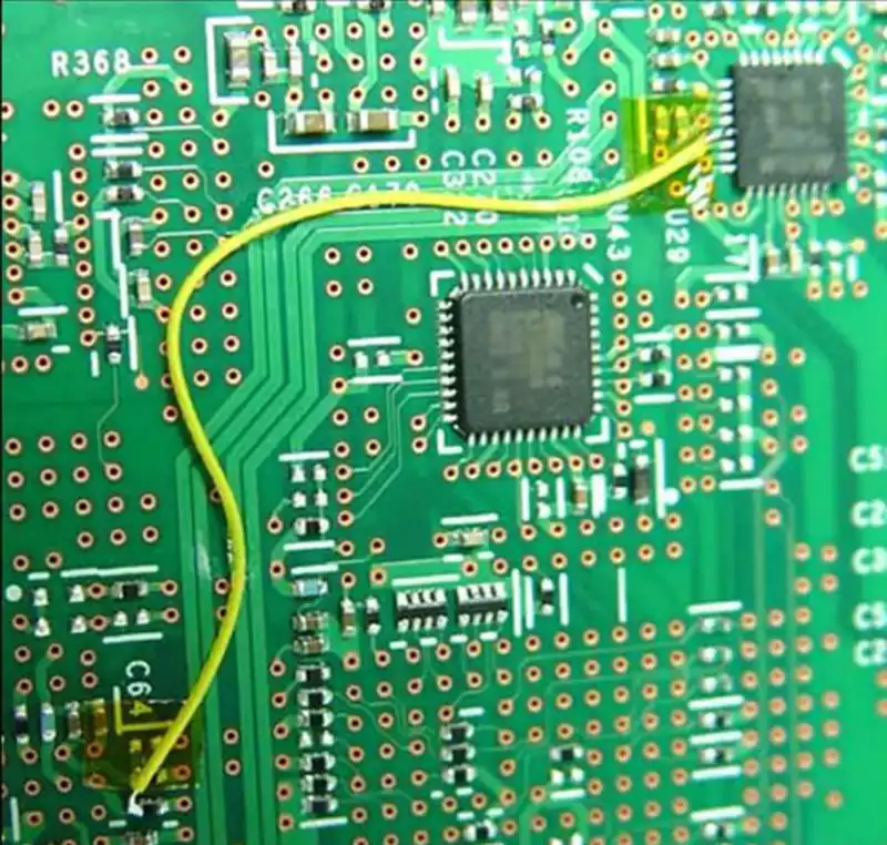
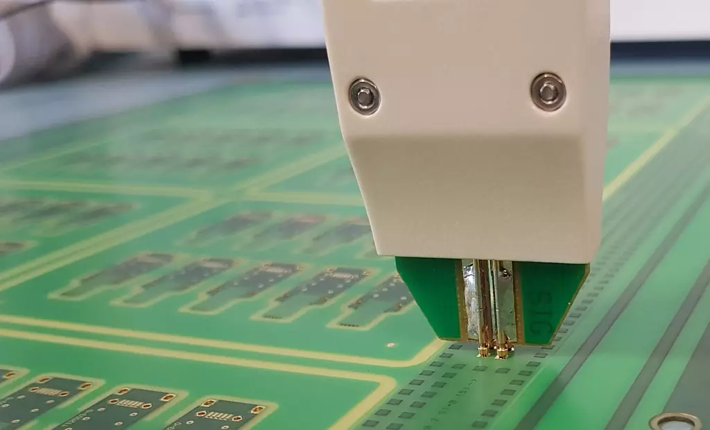
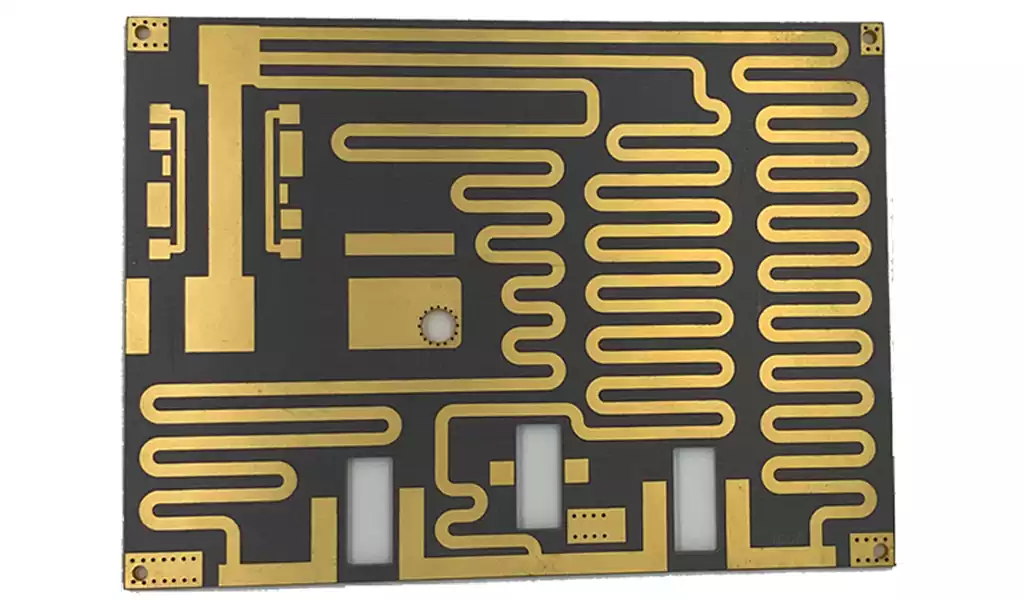
The thermostat circuit board is the control centre of the thermostat, which integrates temperature sensors, control circuits and drive circuits and other functional modules. The temperature sensor is responsible for real-time monitoring of the ambient temperature and transmits the signal to the control circuit. The control circuit compares the preset temperature value with the current ambient temperature and controls the switching of the heating or cooling equipment through the drive circuit, thus maintaining the ambient temperature within a constant range.Regular testing of thermostat circuit boards ensures proper functioning and avoids unnecessary energy consumption and malfunctioning.
The main functions of thermostat circuit board
- Temperature monitoring and control: the thermostat circuit board can monitor the ambient temperature in real time and automatically adjust it according to the preset value to ensure a stable ambient temperature.
- Energy saving and environmental protection: through precise control of the switch of heating or cooling equipment, the thermostat circuit board helps to reduce energy consumption and achieve energy saving and environmental protection.
- Safety protection: the protection circuit on the circuit board can cut off the power supply in time when the equipment fails to ensure the safety of use.
How to test the thermostat circuit board
Before testing the thermostat circuit board, you need to prepare the following tools:
Multi-meter: for measuring voltage, impedance and current to verify the normal working condition of the circuit.
Screwdriver: for disassembling the thermostat case and removing the circuit board.
Soldering tools: If faulty components need to be replaced, soldering tools will be necessary.
Static protection bracelet: to avoid static electricity damage to the circuit board, using a static protection bracelet is a wise choice.

Steps to test the thermostat circuit board:
- Switch off the power
Before performing any tests, first ensure that the power to the thermostat is switched off. This step is crucial to avoid electric shocks and damage to the device. - Disassemble the Thermostat
Using a screwdriver, carefully remove the thermostat’s case to expose the internal circuit board. During disassembly, note down the location of the removed screws and connecting wires for subsequent reassembly. - Check for visible damage
Perform a visual inspection of the circuit board, looking for any possible visible damage such as burnt components, broken solder joints or aged capacitors. If visibly faulty components are found, they may need to be replaced. - Measurement with a multi-meter
Measure the voltage: Set the multi-meter to AC voltage and measure the power port voltage of the board. Under normal conditions, the thermostat should receive the specified operating voltage (usually 24V AC). If the voltage is abnormal, the problem may be in the transformer or power cord.
Measure impedance: Set the multi-meter to resistance and measure the impedance values of each component on the board, such as resistors and capacitors. Check that these values match the markings on the board.
Measurement of current: When required, the current through the circuit board can be measured to confirm that the thermostat is functioning properly under operating conditions.
- Test the control signals
If the thermostat is equipped with a control function,you can simulate different temperature conditions and observe whether the circuit board responds correctly. Check that the thermostat turns on and off the appropriate heating or cooling equipment properly by adjusting its settings.
Troubleshooting
If a problem is found with the thermostat circuit board during testing,the following troubleshooting measures can be taken:
Power supply problems:If the voltage measurement is not normal,check the transformer and power supply wiring to make sure there are no breaks or shorts.
Poor solder joints:If you find loose or open solder joints,you can re-solder the relevant components to ensure a firm connection.
Replacement of components: If a component is found to be damaged (e.g.,capacitor or resistor burned out),replace the corresponding component according to the specifications of the circuit board.
Reboot Quiz: After completing all checks and repairs, reassemble the thermostat, switch on the power and test its function.
Knowing how to test the thermostat circuit board is the key to ensure stable temperature control.Through meticulous testing and reasonable repair,we can effectively solve the circuit board problem, restore the thermostat to work normally and create a comfortable environment for people.


