What is flexible pcb?It is a special type of printed circuit board that is made of a flexible substrate with excellent bendability and lightweight. Compared to traditional rigid circuit boards, FPC can adapt to a variety of complex application scenarios and is therefore widely used in consumer electronics, medical devices, automotive electronics, aerospace, robotics, and other fields.
Flexible PCB (FPC) has the following advantages over traditional rigid printed circuit boards:
Bendability and Flexibility: FPC is made of flexible materials that can accommodate a variety of curved and twisted shapes, making electronic products thinner, lighter, and more portable.
High-density wiring: realize high-density wiring with smaller line widths and spacing to meet the growing functional requirements of electronic products.
Reliability: high reliability and stability, can withstand multiple bending and twisting and is not easy to break and other phenomena.
Cost-effective: A relatively low manufacturing cost can reduce the cost of electronic products.
Environmentally friendly: the materials and processes used in the manufacturing process of FPC have less impact on the environment, in line with the requirements of green environmental protection.
Easy to assemble and repair: The design of FPC makes the assembly and repair of components easier and faster.
Easy to expand: adapted to a variety of expansion modules and interfaces, which is convenient for upgrading and expanding the functions of electronic products.
Overall, the advantages of flexible pcb (FPC) is mainly in the areas of bendability and flexibility, high-density wiring, reliability, cost-effectiveness, environmental friendliness, ease of assembly and maintenance, and ease of expansion. These advantages have led to the widespread use of FPCs in electronic products, especially in areas that require a high degree of integration and lightweight, such as cell phones, tablet PCs, wearable devices, and so on.
Flexible Printed Circuit Board (FPC) Material Requirements.
Substrate: The substrate of FPC requires excellent flexibility, heat resistance, insulation, and processability. Commonly used substrates are polyimide (PI), polyester (PET), and polyetherimide. These materials have high heat resistance, insulation, and chemical stability, and can meet the needs of FPC applications.
Copper foil: Copper foil is the conductive material for FPC, which requires high conductivity, high elongation, and low stress. Commonly used copper foils are calendered copper foil and electrolytic copper foil, of which calendered copper foil has better mechanical properties and conductive properties, suitable for demanding applications.
Insulation film: Insulation film is the insulating material of FPC, which requires high insulation, heat resistance, chemical resistance, and good processing performance. Commonly used insulating films include polyimide film, polyester film, and fluoroplastic film.
Adhesive: adhesive is the insulating film, conductive layer, and substrate bonded together in the material, requiring excellent adhesion, heat resistance, insulation, and chemical stability. Commonly used adhesives are epoxy resin and acrylic resin.
Covering film: covering film is covered in the FPC surface of the protective layer, and requires excellent wear resistance, heat resistance, and insulation. Commonly used cover films include polyimide film and polyester film.
Flex substrate can be classified according to different ways of classification, the following are several common ways of classification:
Classification according to the number of layers: can be divided into four types: single panel, double-sided board, multilayer board and just flexible circuit board.
According to the substrate classification: can be divided into adhesive flexible boards and non-adhesive flexible boards. Among them, the price of a non-glued flexible board is much higher than the flexible board with glue, but its flexibility, copper foil, and substrate bonding, pad flatness, and other parameters are also better than glued flexible board.
According to the through-hole with or without copper classification: can be divided into two types of copper through-hole and no copper through-hole.
According to the structure classification: can be divided into single-sided, double-sided, multi-layer flexible board. Among them, multi-layer flexible board is made of multi-layer single-sided board or double-sided board bonding, which can increase the area of wiring.
According to the wiring density classification: can be divided into ordinary type and high density type. High-density type flexible printed circuit boards have higher wiring density, which can meet the requirements of higher performance.
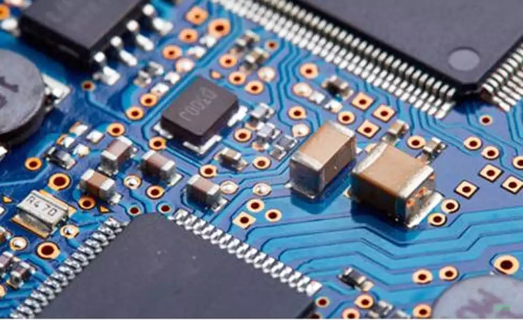
Flexible printed circuit board soldering steps:
Apply flux on the pads and process them once with a soldering iron to avoid poor tinning or oxidization of the pads leading to poor soldering, and the chips generally do not need to be processed.
Use tweezers to carefully place the PQFP chip on the PCB board, taking care not to damage the pins. Align it with the pads and place the chip in the correct orientation. Adjust the temperature of the soldering iron to over 300 degrees Celsius, stick a small amount of solder on the tip of the iron, press down the aligned chip with a tool to solder the diagonal and then recheck the position of the chip to see if it is aligned. If necessary, adjust or disassemble and recalibrate on the PCB board.
When starting to solder the pins, solder should be added to the tip of the soldering iron, and all pins should be coated with flux and kept wet. Touch the end of each pin of the chip with the tip of the soldering iron until you see the solder flow into the pin. Keep the soldering iron parallel to the pins while soldering to prevent overlap from too much solder.
After soldering all pins completely, soak all pins with flux to clean the solder. Suck up excess solder to eliminate any shorts and overlaps. Afterward, use tweezers to check for false soldering. Once the inspection is complete, remove the flux from the board by soaking a stiff bristle brush in alcohol and carefully wiping in the direction of the pins until the flux disappears.
Resistive components are relatively easy to solder. You can start by putting tin on one solder joint, at one end of the part, clamp it with pliers, and solder one end to see if it is correct; if it has been put in place, then solder the other end.
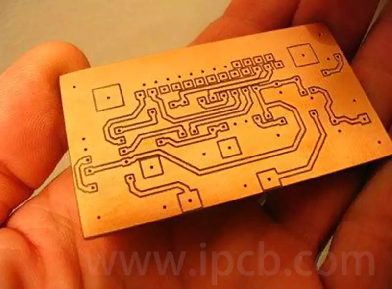
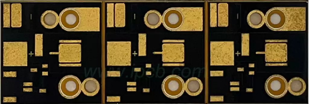
Gold finger process for flexible pcb:
Soldermask window design: To facilitate the insertion of the card, the position of the “gold finger” is not solder masked, and all the windows are opened for processing. This ensures that the gold finger can be smoothly inserted into the card slot during use, and the gold finger in the card slot is not easily covered by solder ink, improving the reliability of use.
Board corner processing design: To facilitate the insertion of the card, the “gold finger” position of the shape of the line needs to be chamfered, as for the beveled or rounded, according to personal preference design. If the shape of the board corners is not chamfered, the right angle will hurt the card slot when inserting and unplugging, resulting in lower reliability of the product.
Line layer copper design: To facilitate card insertion, the outer surface of the “gold finger” area is best not to do copper design. If two or more of them are in the same network, the effect of the copper paving design is that many of them are connected into one piece, then the product produced is not a single “gold finger”, which will affect the convenience of insertion and removal.
Soldermask Window Treatment: To increase the wear resistance of the gold finger, the gold finger usually needs to be plated with hard gold (gold compounds). Gold fingers need to be chamfered, usually at 45°. If there is no chamfer in the design, there is a problem; 45° chamfer in the PCB.
Immersion tin, immersion silver pads need to be a minimum distance of 14 mil from the top of the finger; it is recommended that the design of the pads from the finger more than 1mm, including the over-hole pads; the surface layer of the gold finger do not lay copper; the gold finger inner layer of all layers need to be done to deal with the copper cut, usually cut copper width of 3mm; you can do a half-finger cut copper and the whole finger cut copper.
The area of “gold finger and tin finger” should be opened with a window, which is about 10MIL larger than the board edge; the window is not allowed to be opened for the aperture within 2MM of “gold finger”.
Flexible Printed Circuit Boards Application Areas.
Consumer electronics: these printed circuit board are used in large numbers for the internal circuits of electronic devices such as cell phones, tablet PCs, and laptops. They provide high-density, high-reliability circuit connections while realizing thin and light products.
Medical devices: FPCs are widely used in the medical field for implantable devices, diagnostic instruments, etc. due to their excellent bending properties and biocompatibility.
Automotive electronics: As the automotive industry develops towards intelligence and electrification, FPCs are more and more widely used in automotive electronics, such as in-vehicle entertainment systems, navigation systems, and autonomous driving systems.
Aerospace: FPCs are mainly used in the aerospace field to connect and control various sensors and actuators, as they can maintain stable performance in extreme environments.
Robotics: Flexible Printed Circuit Boards (FPCs) provide efficient and reliable circuit connections for robots, making their movements more flexible and precise.
Flexible pcb is becoming increasingly important as key components in modern electronic devices. With the continuous innovation of technology and expanding market demand, FPC will be widely used in more fields, injecting new vitality into the development of electronic equipment!