In the manufacturing and repair of electronic products, soldering electronic components constitutes a fundamental and critical process. To ensure the proper functionality and long-term stability of circuit boards, strict adherence to a series of operational protocols is required from component preparation through to the final completion of soldering.
- Component Lead Shaping
To ensure electronic components are neatly arranged and uniformly presented on printed circuit boards, effectively preventing faults such as cold solder joints, shaping the component leads is crucial. This operation is typically accomplished using needle-nose pliers or tweezers. Methods for shaping component leads are diverse, with common techniques including basic shaping, bending shaping, vertical insertion shaping, and integrated circuit shaping. - Pre-Soldering Treatment of Electronic Component Leads and Wire Terminals
To guarantee soldering quality, impurities must be removed from leads and tin-dipping performed prior to component soldering. For insulated wires, cut to the required length first, then determine the stripping length based on the connection method and strip accordingly. For multi-strand wires, twist the ends and apply solder. This ensures good electrical conductivity after connection to the circuit and enables the leads to withstand a certain amount of tension, preventing breakage. - Lead Displacement Dimension Inspection
Axially symmetrical electronic components such as resistors, capacitors, and semiconductor devices are typically mounted using horizontal or vertical insertion methods. The specific insertion method selected must be determined according to the circuit board design requirements. After components are mounted onto the circuit board, a certain length of lead should be left protruding through the pad, generally maintained at approximately 1–2 mm. For straight insertion, leads pass through the pad without bending, facilitating insertion soldering. Semi-bent leads are angled at 45 degrees, offering moderate mechanical strength. Fully bent leads are angled approximately 90 degrees, providing higher mechanical strength, though attention must be paid to the direction of lead bending within the pad. - Electronic Component Soldering Procedures
When soldering circuits, divide the printed circuit board into functional units. Typically commence soldering from signal input points, proceeding sequentially. Adhere to the principle of soldering smaller components before larger ones. When soldering resistors, ensure both ends are aligned vertically. When soldering capacitors, ensure correct polarity (‘+’ and ‘-’) is maintained; when soldering diodes, do not reverse the anode and cathode polarities; when soldering transistors, minimise soldering time and use tweezers to hold the leads to aid heat dissipation.
When soldering integrated circuits, first solder the two diagonally opposite pins, then proceed sequentially from left to right and top to bottom. During soldering, the initial amount of solder on the iron tip should suffice for soldering 2-3 pins. When soldering, first touch the iron tip to the copper foil on the printed circuit board. Once the solder has flowed to the base of the integrated circuit pin, then touch the iron tip to the pin. Contact time should not exceed 3 seconds, and ensure the solder evenly coats the pin. After soldering, inspect for missed solder joints, short circuits, or cold solder joints, and clean excess solder from the joints.
Surface Mount Technology
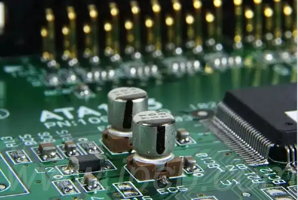
Surface Mount Technology (SMT) is a technique whereby components are directly soldered onto the surface of a PCB circuit board. Its characteristics include compact footprint, high transmission rates, superior reliability, and low cost. The two primary soldering methods for surface-mount electronic components are as follows:
- Soldering Chip Components
Chip components typically encompass small surface-mount resistors, capacitors, diodes, transistors, etc. Their pins are flat and can only be inserted into the board from one direction. Soldering is achieved by heating the joint with hot air, melting the solder to secure the electronic component. - Soldering Ball Grid Array (BGA) Components
Ball grid array components, such as chipsets and FPGAs, feature spherical pins. These are soldered onto the PCB board using hot-air reflow heating.
Through-Hole Mounting
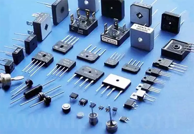
Through-Hole Mounting (THM) involves inserting components into PCB holes and connecting them to the board via soldering. This method offers stable electrical performance, high repairability, and suitability for high-load, high-temperature environments. Common methods for installing through-hole electronic components include:
- Wave Soldering
Through-hole component leads are inserted into PCB holes and secured via wave soldering, connecting the component to the PCB boards. This method is typically used for medium-volume electronics production. - Manual Soldering
Manual soldering involves inserting the component leads individually into PCB holes and securing them through hand soldering. This method is suitable for small-batch production and circuit board repairs.
Soldering Quality Inspection
① Visual Inspection
Assess soldering quality compliance by examining the appearance of soldered joints. Check for missed solder joints, residual flux around solder points, solder bridges or short circuits, cracks in pads, smoothness of solder joints, and the absence of solder wicks.
② Manual tactile inspection
Touch electronic components to detect any looseness or weak soldering. Alternatively, gently pull component leads with tweezers to verify stability. Simultaneously, gently wiggle the solder joint to observe whether any solder has detached.
To ensure the electrical connection reliability of the final product, solder joints must undergo quality inspection after soldering. This includes visual inspection, such as checking for missed solder joints, bridging, or abnormal joint shapes. Additionally, physical contact testing, such as gently tugging electronic component leads, can be performed to confirm the mechanical strength of the solder joints.
