What is millimeter wave radar?It is working in the millimeter wave band (millimeter wave) detection radar. Usually millimeter wave refers to the 30 to 300 GHz frequency domain (wavelength of 1 to 10 mm). The wavelength of millimeter wave is between microwave and centimeter wave, so millimeter wave radar has some advantages of both microwave radar and photoelectric radar.
It uses millimeter waves as electromagnetic wave transmission signals to capture and process the reflected signals of electromagnetic waves passing through obstacles in the path to obtain information such as the speed, distance, azimuth and altitude of the target object.
Millimeter waves have a wavelength range of 0-10mm, which is considered a short wavelength in the electromagnetic spectrum. The use of millimeter wave as an electromagnetic signal can obtain highly accurate ranging information,while the antenna can be made smaller and more compact to reduce the size of the device. Millimeter-wave systems operating at 76-81GHz (corresponding to a wavelength of about 4mm) will be able to detect movements as small as a few millimeters.
It has a short wavelength, wide bandwidth (large frequency range), penetration ability, these characteristics form the advantages of millimeter-wave radar.
- Strong penetrating ability, not affected by weather. Atmospheric propagation of the radar band has an attenuation effect, millimeter-wave radar, whether in clean air or in the rain, smoke, pollution in the attenuation is weaker than infrared, microwave, etc., with a stronger penetration capability. Millimeter-wave radar narrow beam, wide band, high resolution, in the atmospheric window band is not affected by day and night has the characteristics of all-weather.
- Small and compact size, high recognition accuracy. Millimeter wave wavelength is short, the antenna caliber is small, the component size is small, which makes the millimeter wave radar system small size and light weight, easy to install in the car. For the same object, millimeter wave radar has a large cross-sectional area and high sensitivity, which can detect and locate small targets with higher recognition accuracy.
- Long-range sensing and detection can be realized. It is divided into long range radar (LRR) and close range radar (SRR), due to the millimeter wave attenuation in the atmosphere, so it can be detected and sensed to a longer distance, of which the long range radar can achieve more than 200m perception and detection.
Classification
① By Frequency: There are three types: 4GHz, 77GHz and 79GHz.
② By detection distance:
Short-range millimeter wave radar (SRR): detection distance is less than 60 meters.
Medium-range millimeter wave radar (MRR): detection distance of about 100 meters.
Long-range Millimeter Wave Radar (LRR): detection distance greater than 200 meters.
③ By usage:
Corner radar:usually SRR,used for Blind Spot Detection (BSD),Lane Change Assist (LCA) and Front/Rear Cross Traffic Alert (F/RCTA).
Front radar:usually MRR and LRR, used for Automatic Emergency Braking (AEB) and Adaptive Cruise Control (ACC).
PCB design and material usage for mmwave radar
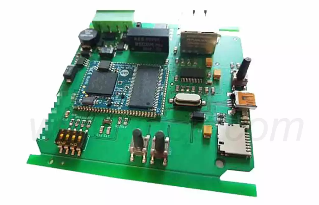
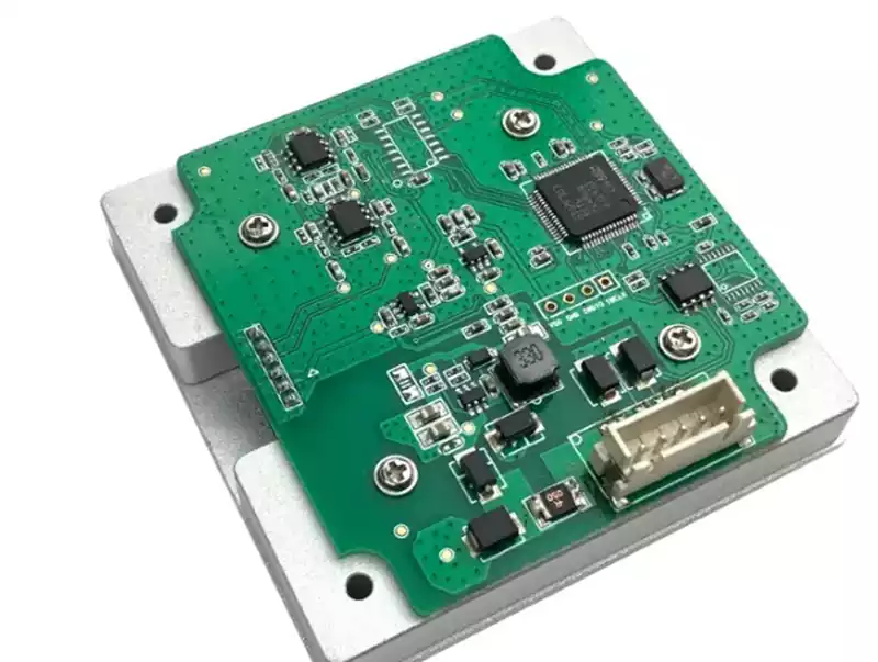
Most of the millimeter wave radars use a complete single chip solution such as TI, Infineon or NXP, which integrates an RF front-end, a signal processing unit and a control unit on-chip to provide multiple signal transmitting and receiving channels. The PCB board design of the radar module is mainly done in the following ways:
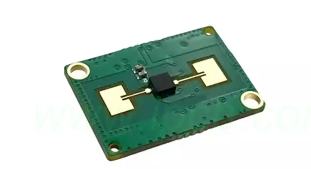
Ultra-low loss PCB material is used as the carrier board for the uppermost antenna design, the antenna design usually uses a microstrip patch antenna, and the second layer of the stack is used as the ground layer for the antenna and its feed line. All other PCB materials of the stack are made of FR-4. This design is relatively simple, easy to process and low cost. However, due to the thin thickness of the ultra-low loss PCB material (usually 0.127mm), the effect of copper foil roughness on loss and consistency needs to be paid attention to. At the same time microstrip patch antenna narrower feed line need to pay attention to the processing of line width accuracy control.
Dielectric integrated waveguide (SIW) circuits are used instead of microstrip patch antennas for antenna design of radar.In addition to the antenna, the other PCB stacks use FR-4 material as the radar control and power supply layer.The SIW antenna design still uses ultra-low loss PCB material to reduce loss and increase antenna radiation.The thickness of the material is usually chosen to increase the bandwidth of the thicker PCB to minimize the effect of copper foil roughness,while there is no process problems when processing narrower line widths.But need to pay attention to the SIW over-hole processing and positional accuracy issues.
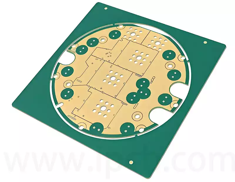
Design multilayer board stacks using ultra-low loss materials.Depending on the requirements,choose to use ultra-low-loss materials for several or all of the stacked layers. This design approach can further reduce the size of the radar module while increasing the flexibility and integration of the circuit design. However, the disadvantages are the relatively high cost and the relatively complex processing.
4D millimeter wave radar, which adds vertical altitude detection to the traditional millimeter wave radar’s three dimensions of distance, speed and azimuth, forming a four-dimensional information input.
Difficulties of 4D millimeter wave radar
The main difficulties of millimeter wave radar, including 4D, lie in antenna design, software algorithms, especially software algorithms.
① Antenna design:
Antenna design is one of the key aspects of each radar manufacturer to be able to make differentiation, determining the azimuth and pitch angle performance.
② Software Algorithm
Software algorithms include signal processing algorithms, data processing algorithms, respectively, for the “signal processing” and “data processing” two radar computation links, the former in the DSP calculation, the latter in the MCU calculation.
At present, the software algorithm has two new technologies:
Super-resolution algorithms: super-resolution algorithm class is to convert low-resolution images into high-resolution images, such as AI processing images;
Virtual Aperture Imaging Algorithm: software algorithms can make apparent performance indicators such as angular resolution better than the hardware more powerful radar.
At present, the main difficulty of 4D millimeter wave is the algorithm, of course, the continuous improvement of hardware performance will continue to improve the basic performance.
When designing PCB (Printed Circuit Board) materials for 4D millimeter wave radar, their comprehensive performance needs to be carefully considered to ensure high performance and accuracy of the radar system. The primary focus is on the electrical properties of the material, of which stable dielectric constant and low-loss characteristics are key, which are directly related to the phase accuracy of the antenna’s transceiver, thereby improving antenna gain, scanning range, and radar detection and positioning accuracy. This stability requires not only consistency across batches of material, but also minimal variation within individual PCBs to maintain excellent electrical stability.
The surface roughness of copper foils should also not be overlooked, especially in ultra-thin materials where high precision is required, as it has a significant impact on circuit performance. Rough copper foils not only have a high degree of variability in themselves, but can also cause significant fluctuations in dielectric constant and loss, which can interfere with the phase characteristics of millimeter waves, thus affecting radar performance.
In addition, the reliability of the material is the basis for ensuring the long-term stable operation of the radar. This includes high reliability in the PCB manufacturing process (e.g., stacking, drilling, copper foil adhesion, etc.), as well as the stability of the material in long-term use and under various environmental conditions. Specifically, materials need to be able to resist the degradation of electrical properties brought about by changes in time, temperature and humidity, which is particularly important for automotive safety systems.
As 4D millimeter-wave radar technology has evolved, its PCB design has undergone significant changes. In order to cope with the higher demand for information sending and receiving and point cloud imaging capability, the RF board area has been significantly expanded, about three times that of the traditional mmwave radar, while the number of PCB layers has also been increased from the traditional 6 layers to 8 to 10 layers to adapt to more complex data processing and transmission requirements.
In terms of material selection, PCB boards have also been upgraded,leaping from traditional high-frequency PTFE materials (e.g., RO4850/RO4350) to higher-level similar materials (e.g., RO3003/RO3006), and these new materials, although more costly (about three times as much as their predecessors), have significantly improved their high-frequency performance to provide a more superior signal transmission and processing environment for 4D millimeter-wave radars, ensuring that the radar system is more complex and has more data processing and transmission requirements and processing environment, to ensure the overall effectiveness of the radar system.
The continuous innovation of 4D millimeter wave radar technology and PCB design will jointly shape a brand new pattern in the field of automatic driving, ensure the safe driving of vehicles, and lead the way of travel to intelligent and efficient.