The Fundamental Role and Industry Significance of NPTH PCB Manufacturing
In mature electronic manufacturing systems, PCBs have become the structural foundation and signal carrier for all electronic devices. However, beyond frequently discussed topics such as routing, pads, impedance, and material stack-up, there is another often overlooked but extremely crucial structure—NPTH, or non-metallic vias. While they don’t carry electrical transmission like signal vias, blind vias, or buried vias, nor do they directly participate in soldering like pads, NPTHs play a far more important role in a complete circuit board than many people realize. They influence mechanical assembly, structural strength, testing methods, connection accuracy, and even the lifespan and reliability of the entire product.
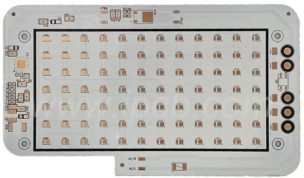
Traditionally, holes seem to be merely places to “pass through,” and people often consider electrically related metallized vias to be the design focus. However, in actual production, almost every screw hole, positioning hole, panelization process hole, jig hole, and support hole for component pins belongs to NPTH. They form the connection foundation of the entire structure, making the PCB not only a signal network but also a structural component capable of stably withstanding assembly and mechanical stresses. In other words, if metallized vias perform an “electrical function,” then NPTHs perform a “mechanical function,” serving as an indispensable core component for soldering, mounting, and securing the entire circuit board.
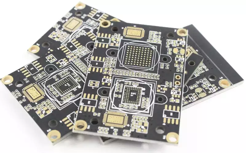
It’s worth noting that the design and manufacturing of NPTHs are not as simple as they appear. Although they do not conduct current, they are still affected by factors such as drilling precision, tempering tool life, board thickness tolerance, and residual stress from machining. For example, when assembling screws, excessive deviation in the NPTH hole diameter can lead to loosening or stripping; if the hole wall is rough or the diameter is too small, mechanical stress during assembly will concentrate in localized areas, forming potential cracks. Furthermore, for products requiring high structural precision, such as industrial cameras, base station filters, and medical devices, NPTH positional deviations can even affect the overall performance of optical alignment or RF structures. Therefore, the machining precision of NPTHs not only affects whether the PCB can be “mounted,” but also whether the device can “operate stably for a long time.”
The presence of NPTHs also affects the PCBA manufacturing process. For example, during the hot air assembly process before SMT, NPTH (NP Heat Transfer) alters airflow and heat distribution, affecting heating uniformity. In wave soldering, improper NPTH arrangement can allow molten solder to seep through gaps, causing contamination. In the testing phase, the precision of the fixture holes determines the accuracy of the press positioning; poor NPTH processing quality directly leads to misalignment of test points and probes, making ICT (In-Process Testing) or FCT (Fixed-Process Testing) impossible. In short, NPTH is an “invisible critical point” that permeates multiple processes, including PCB manufacturing, SMT assembly, through-hole soldering, testing and assembly, and final assembly.
In certain industries, the significance of NPTH even rises to the level of “influencing product success or failure.” For example, in the BMS (Battery Management System) of new energy vehicles, battery modules typically need to be secured to the housing or heat sink via screw holes; in drone flight control and camera modules, NPTH (NP-hardened core) plays a crucial structural role in vibration damping, positioning, and sensor optical axis alignment; in high-speed server applications, NPTH is involved in fixing large heat sinks and must therefore withstand the mechanical stress caused by cyclic thermal expansion. These fields place extremely high demands on the NPTH’s hole diameter accuracy, concentricity, hole wall quality, and board edge distance; any minute error can affect the stability and reliability of the final product.
More importantly, the processing method for NPTH is fundamentally different from that of PTH (Plain Core). NPTH cannot have copper walls, nor can it be partially metallized in subsequent electroplating processes. Therefore, NPTH typically employs independent drilling or secondary blanking processes, and must be clearly distinguished on drawings to avoid confusion. If engineers do not clearly identify NPTH in Gerber or drilling documents, manufacturers may mistakenly treat it as PTH, resulting in copper plating on the hole walls, which in turn affects structural dimensions and may even cause assembly interference. Such errors are extremely costly in mass-produced products, requiring extensive rework or even complete batch scrapping. Therefore, for every engineer involved in the design process, understanding the rules of NPTH (NP-Through Hole) is not only a matter of respect for manufacturing but also a fundamental skill for ensuring successful product implementation.
In summary, NPTH is not a dispensable auxiliary structure in PCB design but a core element that runs through the design, manufacturing, and assembly stages. It determines the mechanical reliability and structural integrity of the PCB throughout the entire product lifecycle and is a crucial foundation for the stable operation of electronic devices. As products evolve towards higher precision, miniaturization, and multi-functionality, the design rules and processing requirements for NPTH will become more stringent, playing an increasingly critical role in future electronic manufacturing.
Mechanical Functions and Structural Design Principles of NPTH
Although NPTH does not carry signals or participate in electrical connections, its mechanical function within the PCB is extremely critical. The position, aperture, mating structure, and spacing of each NPTH directly determine the performance of the circuit board in terms of assembly, fixation, stress, heat dissipation, and lifespan. If circuit design is the prerequisite for a PCB to “operate,” then the mechanical structure of the NPTH (NPonted mounting hole) determines its “long-term stable survival.” For a circuit board to withstand multiple assembly processes, temperature cycles, shocks, vibrations, and complex environmental changes throughout its product lifecycle, the NPTH design must be rigorous, meticulous, and compliant with manufacturing specifications. The following analysis will delve deeper into its mechanical function and design considerations.
The Key Role of NPTH as a Fixing Structure
In practical applications, most products require connections to the housing, heat sink, and structural components via screws, studs, rivets, or struts, and the NPTH is typically the anchor point for these structural components. The mechanical fixing holes must be designed with sufficient diameter and positional accuracy to ensure that structural components do not interfere with board components during assembly, while also considering factors such as insertion force, friction, and thermal expansion and contraction.
For example, in industrial controllers and power modules, equipment is subjected to high temperatures or high loads for extended periods. If the area around the screw mounting holes lacks sufficient mechanical bearing capacity, or if the NPTH hole wall roughness is poor, the holes may gradually enlarge or develop microcracks during use, thus affecting the mounting strength. Many engineers mistakenly believe that as long as the hole diameter meets assembly requirements, it is sufficient. However, in reality, the copper foil clearance around the NPTH, via spacing, board thickness, and fiberglass orientation all affect the stress distribution around the holes. Ignoring these factors can lead to board cracking or delamination under impact or vibration.
Therefore, when designing NPTH mounting holes, it is essential to ensure sufficient mechanical buffer space around the holes, avoid placing them in stress concentration areas, and pay attention to the minimum edge distance of the PCB and structural load changes during multi-board panelization. In high-reliability applications, such as automotive electronics, communication base stations, and drone flight control boards, NPTH mounting holes may even employ increased board thickness or localized reinforcement structures to resist long-term fatigue.
The positioning function of NPTH (Portable Component Hierarchical Hole) ensures assembly consistency and accuracy.
Besides its fixing function, NPTH also plays a crucial role as “positioning holes,” especially in automated production lines, where its significance is even more pronounced. Fixture positioning holes, alignment holes, and panel machining holes are typical applications of NPTH, serving as calibration coordinates in SMT, wave soldering, test fixtures, and automated assembly processes.
If the positioning NPTH has a hole position misalignment, even by only tens of micrometers, it can lead to abnormal component placement, probe misalignment, component soldering deviations, or even render the entire fixture unusable. For example, ICT (In-Circuit Test) testbeds require highly precise positioning holes to ensure probes accurately contact test points; if the hole position misalignment is large, the probes may not be able to contact the solder joints, causing the entire batch of PCBAs to be untestable.
Furthermore, in optical equipment such as camera modules or sensor boards, NPTH also serves as a precise positioning structure for optical axes, lens groups, and light shields. Any aperture or positional error in the NPTH can lead to optical shift, image blurring, or increased noise. Therefore, the hole position tolerances of positioning NPTHs are usually more stringent than those of ordinary mechanical holes, with some high-precision products even requiring a hole position accuracy of ≤ ±0.05mm.
NPTHs participate in heat dissipation, vibration reduction, and structural stress management.
Some engineers mistakenly believe that NPTHs are only related to the “holes” themselves, but in reality, they also participate in PCB heat dissipation and stress management. In areas with dense heat dissipation, properly placed NPTHs can improve airflow paths or provide a fixing structure for heat sinks, allowing for better heat dissipation. In server motherboards or power modules that require large-area heat sinks, the heat sinks are usually secured with NPTHs, and then pressure is distributed by pads with well-matched coefficients of thermal expansion, thus preventing the heat sink from applying concentrated loads to the PCB.
On the other hand, in multilayer boards, due to inconsistent thermal expansion and contraction, different areas will have different stress distributions. The presence of NPTHs can disperse interlayer stress to a certain extent, acting as a kind of “stress relief hole,” which is especially important in areas with thick copper plates or large areas of copper plating. For example, products such as BMS systems in new energy vehicles, power modules in charging piles, and inverters all require NPTH (NP-hardened heat exchanger) placement in critical locations to achieve more balanced structural stress, thereby preventing interlayer delamination or board warping under extreme environments.
Furthermore, NPTH can improve vibration damping performance in vibrating environments. Products such as drones, automotive systems, and robots are subjected to continuous vibration during use; NPTH can transmit and disperse force through screws, adhesive posts, and buffer structures, thus improving overall product reliability.
Key Dimensions and Manufacturing Specifications for NPTH Design
Although NPTH is non-conductive, its manufacturing precision requirements are no less stringent than those for PTH (Plain Hole Heat Exchanger). In the PCB manufacturing process, NPTH must adhere to strict machining specifications, including parameters such as drill hole diameter, hole wall roughness, hole spacing, and board edge distance.
The following points must be considered when designing NPTH (Polyfiber-on-the-Shelf) circuits:
The hole diameter must take into account machining tolerances and structural assembly clearances.
For example, the diameter of screw holes cannot be designed to be exactly the same; an appropriate clearance must be reserved. Otherwise, mechanical friction during assembly may cause the hole wall layer to peel off or the inner layer of the board to be damaged by stress.
NPTH must not be placed too close to the board edge. Being too close to the board edge will cause stress concentration around the hole, easily leading to edge chipping or cracking during V-cutting, board separation, or transportation.
NPTH should not be placed near high-speed traces or precision components.
Although NPTH is non-conductive, mechanical drilling can break the fiberglass structure, causing localized stress changes that may affect the structural integrity of adjacent precision wiring.
A safe distance must be maintained between NPTH and copper foil.
This avoids manufacturing problems such as delamination, exposed copper edges, and mechanical wear.
NPTH does not participate in electroplating; therefore, its drilling and PTH (Polyfiber-on-the-Shelf) processing flows must be strictly separated.
Engineers must clearly distinguish between them in the documentation; otherwise, incorrect plating during manufacturing may easily lead to assembly problems.
In summary, NPTH design is not only about the “location” of the holes, but also about the reliability and manufacturability of the entire PCB structure. It is a crucial component of mechanical structure, assembly process, thermal stress control, and overall durability.
NPTH PCB Manufacturing Process: High-Precision Control from Drilling to Final Inspection
The manufacturing of NPTH PCBs, though a small step in the overall PCB manufacturing process, spans drilling, cleaning, surface treatment, solder masking, shape processing, and even final electrical performance verification. It is a process with extremely high precision requirements. In traditional PCB manufacturing, people often focus more on the electroplating process of PTH (Plate-Through-Hole-Metalled), but the real challenge of NPTH is not “the absence of electroplating,” but rather ensuring that it maintains insulation, dimensional accuracy, and no copper residue on the edges, while preventing “accidental metallization” by other processes. Therefore, NPTH manufacturing is more like a dynamic balance, requiring strict control of the chemical, mechanical, and thermal parameters at each step.
The first step in NPTH is mechanical drilling. Although both NPTH and PTH use CNC drilling machines, NPTH often has stricter tolerance requirements. For example, positioning holes, jig holes, and mounting holes often require a diameter accuracy of ±0.05mm–±0.07mm. Even slight drill bit wear or spindle vibration can lead to out-of-tolerance hole diameters or rough hole walls, affecting final assembly. To avoid these problems, drilling engineers typically use higher-grade drill bit batches in the NPTH process and reduce the number of times a single drill bit is used to ensure consistent hole wall quality.
One of the most critical steps in NPTH after drilling is hole wall cleaning and residue removal. Even if NPTH does not involve electroplating, residual resin dust, fiberglass debris, or drill residue on the hole walls can cause defects in subsequent solder resist, screen printing, and even surface treatment. In severe cases, these residues can absorb solutions and form localized “pseudo-metallization” in copper plating or chemical solutions, causing the NPTH to become semi-conductive. Therefore, factories typically use chemical decontamination solutions and high-pressure water jets to clean the NPTH vias after installation, ensuring that the exposed fiberglass and resin layers on the via walls remain clean and uniform.
During the circuit fabrication stage, another significant challenge for NPTH is preventing accidental metallization of the via walls. In traditional copper plating and electroplating processes, the entire board surface comes into contact with the electroless copper plating solution, meaning that the inner walls of the NPTH vias will naturally adsorb the catalyst. Without proper front-end isolation control, the NPTH can be unintentionally plated with a thin layer of copper, thus losing its insulating properties and even causing short circuits in functional via locations. To address this, manufacturing plants typically employ three measures: Optimizing the pretreatment solution to significantly reduce catalyst adhesion in the NPTH area; Applying a localized protective layer to the NPTH before pattern transfer on the outer layers of the circuitry; and Ensuring that metallization only occurs in the actual circuitry areas through automated development, etching, and stripping systems.
These techniques collectively ensure that the NPTH via walls retain their non-conductive properties—this is the definition of NPTH and its most fundamental function.
After the surface copper layer is applied, the PCB enters the solder mask process. The significance of solder mask for NPTH (NP-Through Holes) goes beyond its standard solder prevention function; more importantly, it prevents solder mask ink from overflowing into the NPTH holes. If solder mask ink accumulates or partially cures and remains inside the hole walls, it will cause the hole diameter to shrink, resulting in poor appearance and even assembly difficulties after curing. Therefore, during solder mask screen printing, it is often necessary to deliberately control the pressure and carefully inspect the NPTH area before exposure and after development to ensure that the hole openings are clean and free of ink residue.
The shaping process (CNC milling or laser cutting) is the NPTH (Non-Plain Hole Layout) is the final critical point for ensuring accuracy. Many NPTHs, especially positioning holes and mounting holes, must maintain their relative positional accuracy with respect to board edges and slots after the outline is completed. For example, if the nozzle positioning holes in SMT assembly are misaligned, it can cause a systemic error in the entire component coordinate system, leading to assembly failures for the entire batch. Therefore, high-quality manufacturers use CCD-assisted positioning during outline processing to ensure that the position of all NPTHs is not shifted due to board stress.
After all mechanical processes are completed, the NPTH PCB enters the final inspection stage. Inspectors typically use hole gauges, 2.5D measuring instruments, and microscopes to check the hole diameter, hole wall cleanliness, burrs, copper residue, and solder mask overflow of the NPTH. Unlike PTHs, NPTHs do not require continuity testing (E-test), but they do undergo electrical insulation testing to ensure that the hole walls of the NPTH do not exhibit electrical conductivity due to accidental copper plating or residue.
In general, manufacturing NPTH PCBs is not simple, involving multiple variables such as drilling precision, chemical control, metallization isolation, solder mask process stability, and shape positioning. Each step requires strict control; otherwise, a defect in a single NPTH via can lead to serious problems in assembly, calibration, or structure of the entire product. This is why excellent PCB factories often invest more testing and monitoring resources in NPTH manufacturing than in ordinary processes, and therefore, the implicit impact of NPTH on product quality is far greater than people imagine.
The Difference Between NPTH and PTH: In-Depth Analysis of Function, Structure, and Process
In the field of PCB manufacturing, NPTH (Non-Plated Through Hole) and PTH (Plated Through Hole) often coexist on the same PCB. While seemingly just a difference between “metallized” and “non-metallized,” the differences between the two are far more profound than imagined when considering their structure, material behavior, electrical properties, and manufacturing risks. If engineers fail to fully understand this difference during the early design phase, it can easily lead to increased processing costs, functional failures, or assembly problems. Conversely, treating NPTH (NP-connected vias) as PTH (partially connected vias) during the manufacturing phase can directly result in irreversible quality defects. Therefore, understanding the difference between the two is a key knowledge point connecting design, process, and quality control.
First, from a structural and functional perspective, the core goal of PTH is to achieve electrical connections. It uses a series of metallization processes such as chemical copper plating and electroplating to connect inner and outer layer circuits through the via walls, enabling signal or power conduction between layers. Therefore, PTH is not just a via; it is part of the circuit, a three-dimensional metal channel, and the fundamental structure for multilayer PCBs. NPTH, on the other hand, is completely different. The essence of NPTH is “mechanical structural vias.” It does not perform any electrical function but is used for mechanical purposes such as screw fastening, positioning, structural fixation, heat dissipation component installation, and test fixture alignment. A typical example is the large mounting holes on a TV motherboard; these holes need to be aligned with the metal bracket or casing without any metal residue posing a risk of conductivity.
Secondly, from the perspective of material behavior and thermal stress characteristics, PTH (Plasma Hole Frame) holes are coated with metallic copper, so the copper layer will experience expansion and contraction during thermal cycling (such as wave soldering and reflow soldering). When the coefficients of thermal expansion (CTE) of the PCB substrate (glass fiber + resin) and the electroplated copper layer are inconsistent, thermal stress will be formed. This stress is particularly significant in high-TG boards, thick copper boards, and HDI boards. NPTH, on the other hand, does not have electroplated copper; its hole walls are entirely composed of the substrate. When heated, it does not form a stress difference at the metal-resin interface, and its thermal stability is actually higher. For this reason, NPTH is often used in locations that need to withstand physical pressure or thermal stress, such as mounting holes for high-current devices and locking holes for heat sink modules, to avoid cracking due to fatigue of the PTH metal layer.
Thirdly, the differences between the two are very significant in terms of manufacturing process difficulty and risk control. The key to PTH is that the electroplating thickness of the hole walls must be uniform and continuous, which determines the reliability and lifespan of the product. While NPTH eliminates electroplating, the challenge lies in “maintaining a non-metallic state.” On a copper plating production line, all vias come into contact with chemical catalysts and copper plating solutions. Without process isolation, protective coatings, or precise parameter management, the via walls of NPTH (NP-metallized hole-and-hole) systems may be passively copper-plated, leading to unintended conductivity or metal residue. This defect is typically only detected under a microscope or during electrical insulation testing. Therefore, NPTH requires no less advanced manufacturing capabilities than PTH (Polymerized Hole-and-Thickness) systems; in high-end manufacturing environments, separate baths or processes are often employed to mitigate metallization risks.
Fourth, there is a significant difference in assembly and end-use. PTH is typically used for through-hole components such as connectors, inductors, and pin headers. It must not only meet conductivity requirements but also withstand soldering temperatures, manual insertion/removal, and mechanical stress. Therefore, via diameter, pad size, ring width, and copper thickness must strictly adhere to IPC standards. NPTH, on the other hand, prioritizes structural requirements. For example, if screw holes are accidentally metallized, tightening screws may damage the copper layer or cause a short circuit; unstable hole diameters in positioning holes can lead to misalignment of the entire product assembly; and inaccurate test positioning holes will prevent the PCBA test fixture from closing, causing production line shutdowns. In other words, although NPTH is not electrical, its impact on the final product assembly is systemic, and poor design or manufacturing can have consequences no less severe than functional defects in the circuit layer.
Finally, the two technologies have completely different considerations regarding cost and manufacturing strategies. Many customers mistakenly believe that NPTH should be cheaper because it is “non-plated,” but the reality is quite the opposite: NPTH manufacturing requires more process isolation, more precision monitoring, and higher drilling requirements, and some precision NPTH (such as alignment holes with ±0.02mm tolerance or laser NPTH) can even cost more than standard PTH. More importantly, distinguishing between PTH and NPTH directly impacts Gerber design and manufacturing procedures. If not clearly labeled in the design documents, factories may mistakenly use NPTH as PTH, or vice versa, leading to serious quality issues. Therefore, top-tier PCB manufacturers typically verify the type, aperture, and production line allocation of NPTH and PTH multiple times during the CAM engineering phase to ensure correct process paths.
Summary
While NPTH and PTH share the common feature of “holes,” their differences in structural function, material behavior, process paths, assembly requirements, and risk control are profound. Understanding and correctly distinguishing between the two is not only a fundamental skill for design engineers but also a crucial aspect of PCB manufacturing quality control. For any product striving for high reliability, the correct design and manufacturing of NPTH and PTH are essential for maintaining stable product operation.
In conclusion, in modern electronics manufacturing, NPTH PCBs are not only part of the structural design but also a key element connecting product mechanical performance, assembly accuracy, and long-term reliability. While it doesn’t handle electrical conduction, it plays an irreplaceable role in functional positioning, heat dissipation and fixation, housing mounting, and production fixture alignment. In contrast, PTH emphasizes electrical performance, while NPTH emphasizes mechanical structure. The difference isn’t simply a matter of “whether it’s metallized,” but rather a comprehensive difference in material behavior, thermal stability, processing paths, testing risks, and product assembly. A high-quality PCB design often doesn’t rely on a single hole type, but rather on the proper differentiation, correct labeling, and precise control of the placement of NPTH and PTH to achieve an optimal balance between electrical performance and structural reliability.
From a manufacturing perspective, the precision requirements for NPTH are often more stringent than they appear. Details such as hole diameter tolerances, drilling burrs, positional misalignment, and the risk of metallization residue directly impact assembly stability and product consistency. Especially in automated assembly, high-speed fixture positioning, metal housing mounting, or the fixation of high-current modules, the processing quality of NPTH becomes a core factor determining yield. For end customers, the reliability of NPTH (Non-Physical Structure) doesn’t immediately surface like electrical defects, but it often accumulates throughout the product lifecycle, manifesting as difficult-to-diagnose issues such as structural loosening, assembly misalignment, or poor heat dissipation. Therefore, prioritizing NPTH during the design phase is crucial for reducing later maintenance costs.
As electronic products continue to evolve towards miniaturization, high integration, and high stability, the role of NPTH becomes increasingly important. Future PCBs will not only rely on precise electrical structures but also require a higher standard of overall coordination across mechanical strength, manufacturability, and system assembly. In this trend, understanding and properly utilizing NPTH is no longer merely supplementary design knowledge but an integral part of professional engineering capabilities. Only by mastering the differences between NPTH and PTH (Physical Structure) and understanding their position in structure, electrical systems, materials, and processes can we truly achieve high-reliability, high-consistency, and high-efficiency electronic product design and manufacturing.