PCB is the basic component of electronic products, any electronic products need to make PCB. then, PCB in electronic products, must be connected with other devices together, this is PCB interconnect. Generally speaking, PCB connection has three aspects: chip to PCB, PCB internal, PCB and external devices.
Chip to PCB interconnect
With chip-to-PCB interconnects, the problem is that the interconnect density is too high, which can cause the basic structure of the PCB material to become a limiting factor in the growth of interconnect density. The solution is to use a local wireless transmitter inside the chip to transmit data to neighboring boards.
Internal Interconnect
Internal PCB interconnections should be based on the following principles: Use high performance PCB with hierarchically controlled insulation constants to manage electromagnetic fields. Avoid the use of leaded components and avoid through-hole processing on sensitive boards, as this process creates wire inductance at the through-hole. Choose a non-chemical nickel or immersion gold plating process to provide a better skin effect for high frequency currents.
External Connections
There are several main types of external connections:
- Wire welding
PCB printed circuit board with wires on the external connection points and components outside the board or other parts can be welded directly, without any connectors. - Line welding
This method is commonly used between the two boards for the 90-degree angle of the connection, the connection becomes a whole PCB components. - Printed board socket
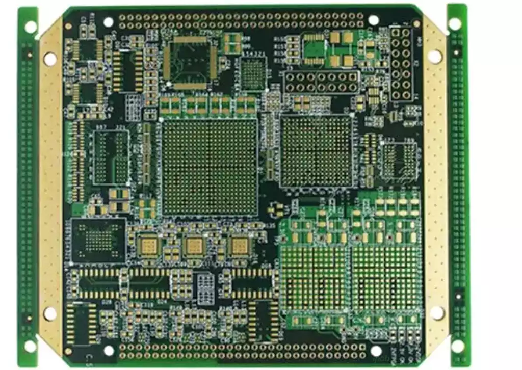
In the more complex instruments and equipment, often use this connection. From the edge of the PCB printed board to make a printed plug, plug part of the size of the socket, the number of contacts, contact distance, positioning holes in the location of the design, so that it matches the special PCB printed board socket. - Standard pin connection
This method is suitable for use in small instruments, through the standard pins will be connected to the two pieces of printed circuit board, the two pieces of printed circuit board is generally parallel or perpendicular.
Printed Circuit Board Connection
Through-hole connection
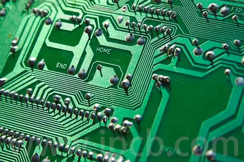
Through-hole connections are one of the most common connections on printed circuit boards. Through-hole connections are usually realized by means of electrolytic copper vias. A physical connection is made between the component and the board by means of a conductor that passes through the electrolytic copper holes and is soldered to the ends of the holes. The advantage of through-hole connections is that they are highly reliable and suitable for all types of cables and components. The disadvantage is that through-hole connections can increase wiring complexity and may limit board design flexibility.
Surface Mount Connections
Surface mount connections are a popular and growing alternative to traditional through-hole connections. Unlike through-hole connections, surface mount connections are made by attaching electronic components directly to the surface of the board and then connecting them to the board through separate copper wires. The advantages of surface mount connections are compactness, flexibility and good scalability. The disadvantage is that the production process involves high-temperature soldering, which may result in broken or shorted solder joints if the soldering temperature is not correct.

Connector and PCB (printed circuit board) connection methods are varied, common connection methods are as follows:
- Soldering connection: This is the most commonly used connection, through the soldering tools such as solder and soldering iron will be components and wires firmly connected to the circuit board.
- Plug-in connection: Using connectors such as pins, sockets or IDC (Insulation Displacement Connection) terminals, components and wires are connected to the PCB board by inserting them into the PCB board or socket.
- Mounted connection: Components and wires are connected to the PWB through crimping, clamping or bonding.
- Flexible connection: the use of spring tabs, plugs and other flexible metal connectors will be components and wires connected to the circuit board.
- Soldering and plugging hybrid connection: a combination of soldering and plugging connection, the use of pins or sockets to connect and soldered to the printed circuit board.
- Soldering perforated connection: components and wires are connected through the perforated aperture on the PCB board and soldered to the PCB board.
- Surface Mount Connection: The surface of the component is soldered directly to the surface of the PCB board, usually using SMT (Surface Mount Technology) for connection.
- Standard pin connection: Used for the external connection of the PCB substrate, especially common in small instruments, through the standard pins will be connected to the two PCB board parallel or perpendicular.
- PCB socket: from the PWB edge of the production of printed plugs, and special PCB plate sockets to match, for multi-board structure of the product.
- Press-fit (crimp) connection. A pin pin is pressed by an external force into a hole smaller than its outer diameter, low cost, high efficiency, simple operation, widely used in communications and computer industries.
- Crimp (cold press) technology: through the crimping pliers or crimping tools to complete the crimping of metal wires and pins, with good airtight and corrosion resistance.
PCB connection technology is the bridge to build electronic products, its importance is self-evident. By continuously optimizing and improving the connection technology, we can improve the performance, reliability and stability of electronic products.


