PCB dielectric thickness is usually the thickness of the glass fibre cloth or other special material used to cover both sides of a printed circuit board (PCB) during the manufacturing process. The choice of dielectric thickness depends on the specific application scenario and requirements of the circuit board. Multilayer board dielectric thickness refers to the thickness of the electrical insulation between each layer of the board and the copper foil in a multilayer board. It is an important part of the composition of the multilayer board, which directly affects the performance of the multilayer board. Usually mil (1mil = 0.0254mm) or um (1um = 0.001mm) as the unit of dielectric thickness.
Classification of PCB dielectric thickness
There are two types of PCB dielectric thickness, namely, the on-board dielectric thickness and the dielectric thickness in the line stack. The on-board dielectric thickness of a circuit board is usually a measure of the thickness of the dielectric layer between the copper foil and the surface of the board. Dielectric thickness in line stacking refers to the thickness of the dielectric layers stacked in a multilayer circuit board.
PCB dielectric thickness factors
Material properties
Substrate type and adhesive content: PCB dielectric thickness is affected by the type of semi-cured sheet (prepreg) and substrate board used, the adhesive content and thickness of semi-cured sheets produced by different manufacturers vary, resulting in different dielectric thicknesses after the press-fit.
Dielectric material compression properties: different resins and fibre materials will have different compression rates during the pressing process, the hardness and flexibility of the material affects the stability of the thickness.
Dielectric constant: the dielectric constant of the material and the thickness of the existence of certain interactions, due to different material properties may lead to thickness adjustment limitations.
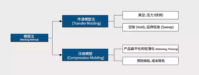
Manufacturing Process
Pressing Process Parameters: Pressure, temperature, time and flatness of the equipment during lamination directly affect the thickness of the layers. Consistent and stable pressure and temperature control is the key to ensuring uniform thickness of the dielectric.
Pressure plate flatness and procedure: Pressing machine pressure plate is flat, pressing procedure is reasonable will affect the uniformity of the media layer and thickness changes.
Incoming material tolerance and raw material consistency: The thickness tolerance of the semi-cured sheet and plate used directly affects the thickness of the final media layer. Achieving stable thickness requires strict control of raw material specifications and batch consistency.
Design and Structure
Line Density and Design Requirements: In order to meet signal impedance and transmission quality, the thickness of the dielectric layer in the design will be adjusted according to the spacing requirements between different circuit layers.
Layer-to-layer stacking structure: The stacking structure of multilayer circuit boards determines the thickness ratios of different dielectric layers, requiring reasonable arrangements for line spacing and insulation layer thickness.
Soldermask thickness: The thickness of the soldermask coating will also change the dielectric environment around the line, indirectly affecting the electrical characteristics of the dielectric layer and the effective thickness.
How to choose the right pcb dielectric thickness and core board thickness
There are other factors to consider when choosing a PCB, such as the design complexity of the board, reliability requirements, process difficulty, and so on. The following are a few selection factors that require attention in actual use:
- According to the circuit board application scenarios for volume analysis, the media thickness and core board thickness to weigh and balance.
- PCB with a greater thickness of the core board, electrical performance will be better, so that the current can be used in a larger scene; and circuit board space is relatively large, the thickness of the core board can effectively reduce the thickness of the circuit board.
- PCB pressure is too large is prone to unanticipated rebound, the smaller the modulus of elasticity of the material and dielectric thickness, there will be a more pronounced rebound. When selecting the right number of circuit boards, the pressure frame needs to be taken into account, thus reducing the occurrence of unanticipated problems.
- For special circuit boards (such as high-frequency circuit boards, microwave circuit boards, optical signal transmission circuit boards, etc.) need to be based on the dielectric constant of the conductive medium and the dielectric loss angle tangent to a reasonable choice, as far as possible to maximise the speed of signal transmission and signal quality.
PCB dielectric thickness has a significant impact on the performance of the printed circuit board, which in turn has a bearing on the life and reliability of the board:
Thermal conductivity, thicker dielectric layers help to improve the heat dissipation of the printed circuit board, and therefore in the connection of high-power electronic components, usually choose a thicker dielectric material.
Reliability, a greater pcb dielectric thickness can enhance the board’s resistance to bending and stretching, thus improving its overall structural stability and reliability.
Cost, media thickness will lead to increased manufacturing costs of printed circuit boards, especially in large-area applications, this cost increase is particularly significant.
The impact of thin pcb dielectric thickness:
- Electrical performance issues
a. Interconnection between sub-circuits: the sub-circuits of the circuit board need to be connected to each other, if the dielectric thickness is thin, the signals of different sub-circuits will interfere with each other, which will lead to poor contact or signal attenuation and other problems.
b. Board Resistance: If the dielectric thickness is thin, the copper layer on the surface of the board will become thinner, resulting in an increase in board resistance and an increase in operating frequency.
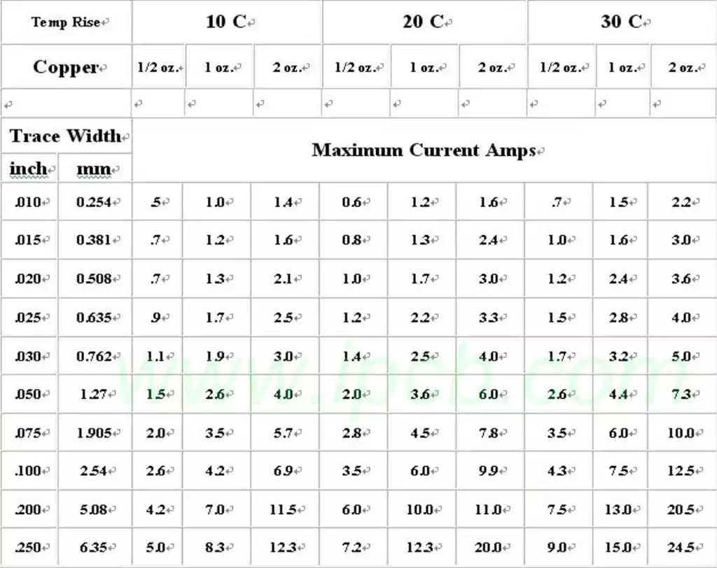
c. Electrical Conductivity: If the dielectric thickness of the board is thin resulting in a thin layer of copper, then a current concentration may occur. This concentration of current may cause the board to catch fire and malfunction, thereby damaging the entire system.
- Structural Problems
a. Insufficient strength: The thin dielectric thickness of the board may lead to insufficient mechanical strength of the board, which is prone to cracking, bending and other problems during use.
b. Poor soldering: If the dielectric thickness of the circuit board is thin, it will lead to poor soldering, because the top of the current density of the soldering point becomes high.
There are two main ways to measure the thickness of circuit board insulation: caliper measurement method and thickness gauge measurement method. Caliper measurement requires the use of tools such as calipers, rulers and miniature screwdrivers to calculate the insulation thickness by measuring the difference between the outer diameter of the wire and the outside of the insulation layer. The thickness gauge method is simpler and more straightforward. Simply place the gauge head on the wire insulation and read the scale to obtain the thickness of the insulation. In the measurement, be sure to pay attention to keep the measurement tool and the wire insulation layer parallel and close to ensure the accuracy of the measurement results.
Proper selection of pcb dielectric thickness is essential to ensure the electrical performance and mechanical strength of the PCB. The correct thickness not only improves heat dissipation and reliability, but also avoids signal interference and structural damage, ensuring stable operation and long-term use of the circuit board.