A pcb motor, also known as a BLDC motor, is a three-phase brushless motor based on the Hall effect, which works by utilizing the current from an electronic controller to generate rotational force inside the motor. This type of motor is widely used in electronic devices such as power tools, automobiles, bicycles, toys, etc. pcb motors utilize printed circuit boards (pcb) as the base structure of the motor rotor, and have a unique product structure and working principle. Its stator consists of a pcb board, coil and magnet, while the rotor consists of a pcb board and permanent magnets attached to it. This structure makes the motor smaller, lighter, and easier to integrate into a variety of devices.
Overview of pcb technology
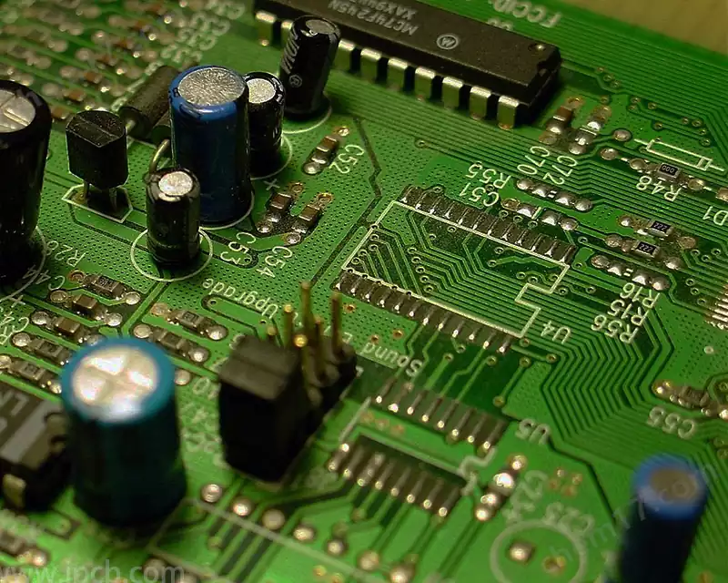
Definition: A pcb (printed circuit board) is an electronic assembly used to mechanically support and connect electronic components. It forms an electrical connection by etching a conductive pattern on an insulating substrate and connecting the electronic components by soldering or other means.
Function:
Mechanical support: provides structural support to hold electronic components in place.
Electrical Connection: Realizes the electrical connection between components through conductive lines.
Thermal Management: Helps dissipate heat and keep electronic equipment at the proper operating temperature.
Electromagnetic shielding: reduces electromagnetic interference and protects circuits from external electromagnetic noise.
Components of pcb
Substrate material: usually epoxy resin glass cloth laminate (FR4), also includes other materials such as polyimide (PI) and aluminum substrate.
Conductive layer: consists of copper foil, which is etched to form a circuit pattern.
Insulating Layer: Insulating material between circuits to ensure electrical isolation between different circuits.
Copper Cladding Layer: A copper layer covering the surface to protect the circuits and prevent oxidation.
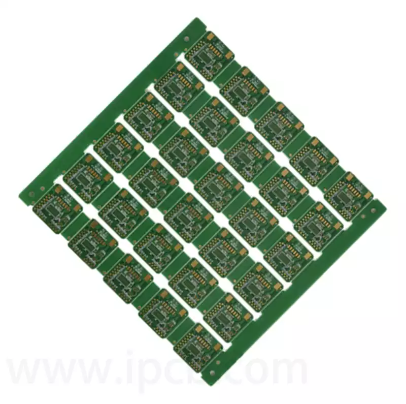
Classification of pcb
Single-sided pcb: wiring on one side only, suitable for simple circuits.
Double-sided pcb: both sides have wiring, through the hole connection, suitable for complex circuits.
Multi-layer pcb: with multiple layers of wiring, connected by inner conductive patterns and via holes, suitable for more complex and high density circuits.
What is a motor stator? The working principle of a motor stator, the motor stator is the stationary part of the motor. In most motors, the stator accomplishes the conversion of electrical energy to mechanical energy by providing a varying rotating magnetic field, which drives the rotor to rotate.
The stator consists of two parts, the core and the windings: the core is usually made of silicon steel sheets laminated together to minimize hysteresis and eddy current losses, and the windings are the wires wound in the slots of the core, which are responsible for generating the magnetic field.
Key elements to consider when designing a motor stator
Core Material
The choice of core material determines the hysteresis and eddy current losses, which have a great impact on the performance and efficiency of the motor. High permeability silicon steel sheets are usually used in the design to improve the efficiency of the magnetic field.
Winding insulation
Copper wire windings need to be well insulated to prevent current leakage and short circuits.
The characteristics of the motor dictate that it needs to run steadily for a long period of time, and therefore the heat dissipation of the motor needs to be considered comprehensively in the design to minimize the accumulation of heat generated during operation. Maintain the temperature of the motor within the range of optimum efficiency.
Processing of pcb motor stators
The design of pcb motor stator is characterized by significant features, usually very dense coil winding, thick copper process, high number of layers, use of high Tg sheet, and high insulation requirements.
The characteristics of pcb motor stator determine a series of difficulties in its processing:
Exposure accuracy: differences in coil exposure accuracy will lead to deviations in parameters between different phases of the motor, thus affecting the operating efficiency of the motor.
Etching link: the difficulty of potion exchange increases, and the amount of side etching becomes larger, which needs to be solved by multiple rapid etching and increasing the etching compensation factor to solve the problem of large amount of side etching.
Lamination link: due to the line gap is deeper, in the case of the same rate of copper residue, you need to choose more than one semi-cured sheet with good fluidity to meet the needs of the resin filling volume. At the same time, it is necessary to add rivets to strengthen the fixation between core boards and reduce the risk of slipping boards. The increase in copper thickness leads to a slower actual heating rate of the board during pressing, and the duration of the high temperature section needs to be increased to increase the curing effect of the semi-cured sheet.
Drilling: thick copper plate thickness of 2.0mm or more, you can use segmented drilling to solve the problem of drilling difficulty, and at the same time, adjust the parameters of the knife speed and the speed of the knife to optimize the quality of the drilling, reduce the speed of the knife, to avoid the problem of pulling the thick copper pads cracked.
Soldermask printing link: due to the line gap is deeper, copper and substrate height difference will lead to oil flow, oil thickness is not enough, line red, pinhole bubbles and other issues, the need to dilute the viscosity of the ink, the use of multiple printings to solve a series of problems soldermask printing.
pcb motorAdvantages of pcb motor.
- Low noise: pcb motors have a simple structure, so there is less of the pushing sound of traditional DC motors. This makes it an ideal motor for use in appliances and electronic devices.
- High Efficiency: pcb motors have a higher conversion efficiency than other DC motors and are about 30% more efficient than conventional motors. The result of this high efficiency is a longer battery life.
- High Reliability: Since this motor does not use consumables such as carbon brushes, it has a much longer life. With a life span of 10,000 hours, pcb motors also last longer than conventional motors.
- Small size: pcb motors have a compact design and are small in size and functional because they do not have components such as carbon brushes.
Disadvantages of pcb motors:
- Higher manufacturing cost: The manufacturing cost of pcb motors is more than double that of conventional motors. This makes it in some large equipment in the field of application limitations.
- control circuit is more complex: because the motor is directly controlled, so the need for specialized circuit control. Therefore, a higher level of technical expertise is required to control or repair pcb motors.
- Smaller torque: The torque of pcb motors is smaller than that of conventional motors, so their application is more limited in certain fields.
Working principle of pcb motor
Motor Principle: The working principle of pcb motors is similar to that of conventional motors, which generate rotational torque through electromagnetic action. The difference is that the pcb motor forms the winding and magnetic field of the motor by arranging conductive lines and electromagnetic materials on the pcb. Current and magnetic field: the current flows through the conductive lines on the pcb to generate a magnetic field, which interacts with a fixed magnet or electromagnetic material to generate torque to drive the motor to rotate.
Design considerations for pcb motors: design requirements size and volume: pcb motor design requires consideration of compact size and volume to accommodate small electronic devices.
Electrical design: This includes the winding design, current path, and layout of the conductive lines of the motor to ensure efficient operation of the motor.
Thermal management: Since motors generate heat during operation, the design of pcb motors must include effective thermal management solutions, such as heat sinks, thermally conductive materials, and so on.
Mechanical design: It is necessary to ensure that the structure of the pcb motor is robust enough to support the mechanical components and workloads of the motor.
Design tools and techniques, pcb design software: circuit design and layout using pcb design software (e.g. Altium Designer, KiCad). The software can help simulate circuit performance and optimize the design. Electromagnetic simulation: Analyze electromagnetic field distribution and optimize motor design through electromagnetic simulation tools (e.g. ANSYS Maxwell, COMSOL Multiphysics). Thermal Simulation: Evaluate the thermal performance of pcb motors using thermal simulation tools to ensure that the motor does not overheat during operation.
Challenges faced by pcb motors
Power density limitations, pcb motors usually do not have the same power density as conventional motors due to material and design limitations of pcb. This can limit their use in high power applications.
Solution: Use high performance materials and optimized design solutions such as increasing copper thickness and using better heat dissipation techniques to increase power density.
Thermal management issues. The heat generated by motors during high power operation may cause the pcb to overheat, affecting motor performance and lifetime. Solution: Solve thermal management problems by improving thermal design, such as adding heat sinks, optimizing thermal conductive materials, and improving thermal convection efficiency.
Mechanical strength. The mechanical strength of pcb motors is usually lower than that of conventional motors, which may limit their use in high-load applications. Solution: Use stronger substrate materials or optimize structural design to improve mechanical strength.
Application of new materials
1.High-performance substrate materials: research and development of new high-performance substrate materials (e.g., high thermal conductivity materials, flexible materials) to enhance the performance and applicability of pcb motors.
- advanced conductive materials: the use of more efficient conductive materials (such as nano-silver, copper plating) to improve the conductivity and efficiency of the motor. Advances in design and manufacturing technology, higher integration: future pcb motors will likely integrate more functions, such as sensors, control circuits, etc., to further reduce the size and improve functionality. 3d printing technology: the application of 3d printing technology to manufacture pcb motors enables more complex structural design and efficient production processes.
Application of new materials
High-performance substrate materials: research and development of new high-performance substrate materials (e.g., high thermal conductivity materials, flexible materials) to enhance the performance and applicability of pcb motors.
advanced conductive materials: the use of more efficient conductive materials (such as nano-silver, copper plating) to improve the conductivity and efficiency of the motor. Advances in design and manufacturing technology, higher integration: future pcb motors will likely integrate more functions, such as sensors, control circuits, etc., to further reduce the size and improve functionality. 3d printing technology: the application of 3d printing technology to manufacture pcb motors enables more complex structural design and efficient production processes.
Expansion of Application Areas
Medical and healthcare: pcb motors are used in more medical and healthcare fields, such as implantable devices and portable diagnostic equipment. Smart Home: Explore the potential of pcb motors in environmental control and smart home systems in smart home devices
The working principle of pcb motors is based on the relationship between voltage, current and magnetic field, and the control of motor steering and speed is realized by controlling the direction and strength of current. Such motors are widely used in industrial automation, robotics, aerospace, and home appliances. For example, in industrial automation, circuit board control motors can be used in various production lines, such as assembly lines and packaging lines, to improve productivity. In the field of robotics, circuit board control motors can realize precise movement and fast response of robots.