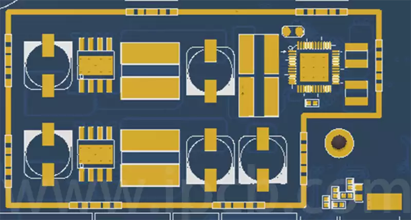
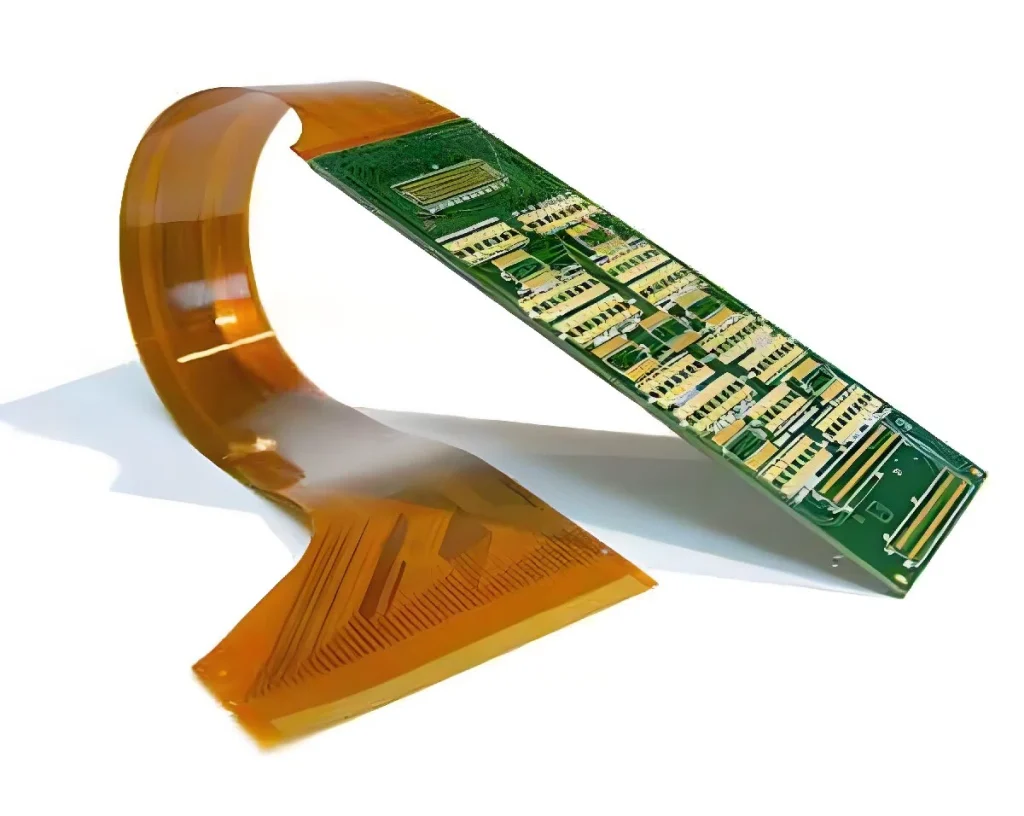
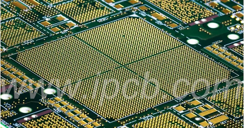
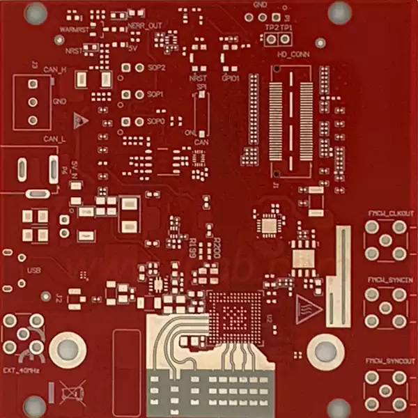
PCB shield cover is a component used to protect the internal components of electronic equipment from electromagnetic interference, generally used in places where it is necessary to prevent the leakage of radiation signals or to avoid the impact of external electric fields, such as communications equipment and computer motherboards commonly used on the PCB board metal sheet cover is a typical example.
PCB shield design: follow 3 iron rules
① Safe spacing
shield body ≥ 1mm from PCB edge to prevent assembly bump;
opening to avoid clock/RF critical signal path to reduce radiation leakage.
② Grounding strategy
must use metal shrapnel / conductive adhesive connection PCB ground layer;
ground contact spacing ≤ 10mm, to ensure low impedance paths.
③ Structural Adaptation
Confirm in advance the risk of interference between the shield and structural components (e.g. heat sinks), and reserve ≥0.5mm clearance.
Single-piece PCB Shielding Frame Design
The single-piece or fixed shield is directly affixed to the PCB through the SMT process, and is often referred to as a Shielding Frame in English. In the design, it is necessary to consider how to effectively isolate the sensitive circuits while ensuring the normal operation of other circuits. Since the single-piece shield is directly affixed to the PCB through the SMT process, the recommended material is Cu-7521 (R-1/2H or R-OH), which has excellent soldering performance. The shielding cover of the open hole design needs to be careful, open hole design to a certain extent will sacrifice the shielding effect, but this is to ensure that the internal devices in the work of the heat dissipation needs. The height of the shield is recommended to be set at 0.25mm, plus the maximum height of the internal device to ensure proper shielding effect. Consideration also needs to be given to reducing the temperature difference between the inside and outside of the shield during the reflow process to ensure robust soldering.
Two-piece PCB Shielding design
The two-piece shield, also often referred to as removable, is designed to be opened directly without the use of tools such as a hot air gun, which brings great convenience for later debugging and maintenance. The design of the two-piece shield is more complex than the single-piece type, so the price is relatively high. Structurally, it consists of a Shielding Frame at the bottom which is soldered to the PCB by SMT and a Shielding Cover at the top, which can be directly fastened to the Shielding Frame for easy disassembly. Usually, the bottom Frame is called Shielding Frame and the top Cover is called Shielding Cover. When choosing the material, the Frame is recommended to be made of white copper because of its excellent tinning performance, while the Cover can be made of tinplate, mainly because of its cost advantage. At the beginning of the project, a two-piece shield is a good choice for ease of debugging. Once the hardware is debugged and stable, you can consider moving to a single-piece shield to reduce the overall cost.

Core Functions of PCB shields
Preventing Electromagnetic Interference (EMI)
The primary function of a shield is to effectively prevent electromagnetic interference. In the complex electronic equipment environment, signal transmission is very susceptible to external sources of interference, which may originate from other electronic equipment, cables or power supplies. Shields can isolate these interfering signals, ensuring the stable operation and reliability of the entire circuit system. Especially in high-frequency or precision circuits, even small interference signals can lead to the failure of the entire circuit, so in the design of these circuits, the role of the shield is crucial. Shields achieve shielding effect by reflecting and absorbing electromagnetic waves, where part of the electromagnetic energy is reflected and the other part is absorbed by the shield.
Protecting Sensitive Components
In addition to electromagnetic shielding, another important role of PCB shields is to physically protect components. Electronic components are generally more fragile, vulnerable to external mechanical forces or electrostatic discharge damage. Shielding covers, usually made of metal materials, can provide an effective physical barrier to prevent components from mechanical damage or electrostatic discharge effects, thereby enhancing the durability and reliability of the entire circuit board.
Enhancing circuit performance
The presence of a pcb shield can also significantly improve the overall performance of a circuit. By effectively isolating interfering signals, shields can reduce the noise level of the circuit system, thereby significantly improving the signal-to-noise ratio of the circuit. In addition,pcb shields help to reduce leakage capacitance and inductance within the circuit board. These parasitic effects are often caused by interference between signal lines on the board, and by suppressing such crosstalk, shields reduce leakage capacitance and inductance, thereby optimising the overall performance of the circuit system.
PCB shields are indispensable components in modern electronic equipment, not only to effectively suppress electromagnetic interference and ensure the purity of signal transmission, but also to provide physical protection for vulnerable electronic components. At the same time, by reducing circuit noise and parasitic effects, the shield significantly improves the overall performance and reliability of the circuit.


