The pcb board pins are an integral part of any electronic device, enabling smooth and reliable transmission of signals and power between different components on a printed circuit board. These connectors come in a variety of types, each with their own unique functions and applications. In this article, we will explore some of the most commonly used pcb solder pins.
Nowadays, many people have problems with their electronic devices, they choose to throw them away directly and buy a new one. In fact, nowadays, problems with some electronic devices are usually some problems with the circuit board, as long as they are rewelded, they can be used again.
Tools and materials required
Soldering tool cloud should have a 25W copper head of small soldering iron, conditions can be used to adjust the temperature and with ESD protection of the soldering station, pay attention to the tip of the soldering iron to be fine, the top of the width can not be greater than 1m to the pointed tweezers can be used to move and fix the chip as well as to check the circuit. Also prepare fine soldering wire and flux, isopropyl alcohol and so on. The purpose of using flux is mainly to increase the fluidity of the solder, so that the solder can be pulled with a soldering iron and rely on the role of surface tension smoothly wrapped in the pins and pads. Use alcohol to remove the flux from the board after soldering.
- In the soldering connection before applying flux on the pad, with a soldering iron to deal with once, so as to avoid bad tinning of the pad or oxidized, resulting in bad welding, the chip is generally not required to deal with.
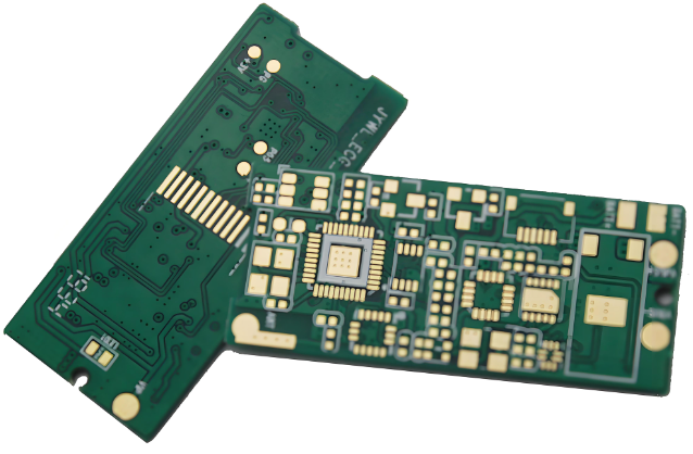
- Use tweezers to carefully put the PQFP chip on the PCB board, pay attention not to damage the pins. Make it aligned with the pad, to ensure that the chip is placed in the right direction. The temperature of the soldering iron to more than 300 degrees Celsius, the tip of the soldering iron tip dipped in a small amount of solder, with a tool to press down on the chip has been aligned with the position of the two diagonal position of the pins with a small amount of flux, still press down on the chip, the welding of the two diagonal position of the pins, so that the chip is fixed and can not be moved. After welding the diagonal to re-check the position of the chip is aligned. If necessary, adjust or remove and re-align the position on the PCB.
- When you start to solder all the pins, you should add solder to the tip of the soldering iron, and apply flux to all the pins to keep them wet. With the tip of the soldering iron to touch the end of each pin of the chip, until you see the solder flow into the pin. When soldering to keep the tip of the soldering iron and the soldered pins in parallel, to prevent the occurrence of overlap due to excessive solder.
- After all pcb solder pins are completed, wet all pins with solder flux to clean the solder. Wick off excess solder where needed to eliminate any shorts and laps. Finally, use tweezers to check for false soldering. After the inspection is complete, remove the flux from the board by dipping a stiff bristle brush in alcohol and wiping carefully along the direction of the pins until the flux disappears.
- SMD resistive components are relatively easy to weld some, you can first point on a soldering point on the tin, and then put on one end of the components, with tweezers to hold the components, welded on one end, and then see if it is put on the right: if it has been put on the right, and then on the other end. To really master the rotten connection skills need a lot of practice
Precautions:
Soldering temperature: avoid soldering iron temperature is too high, so as not to damage the circuit board and components.
The amount of solder: do not use too much solder, so as not to cause short circuits or solder joints too large.
Quality of solder joints: The solder joints should be smooth and even, and there should be no globular solder or false soldering.
Safety: During the welding process, pay attention to ventilation to avoid inhaling solder fumes. When using welding tools, pay attention to avoid burns.
Which is the best pin soldering in circuit board manufacturing?
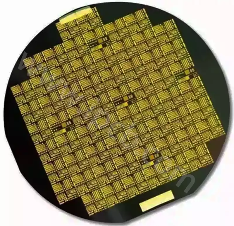
In the manufacturing process of circuit boards, the component pins are usually soldered to the circuit board using the following two methods: one is to directly solder each pin to the circuit board; the other is to paint the pins with solder paste and then put the components and circuit boards into a high-temperature oven to make the paste melt, and then wait for the paste to solidify to realize the welding. The defects of the first method is that when the number of pins, pin density is large one by one welding difficulty, personnel difficult to operate, thus affecting the welding effect. The defect of the second method is that the oven baking temperature is high, usually up to three or four hundred degrees Celsius, making the components or circuit boards with high temperature parts of the abnormal and affect the quality of the product, and if the part of the non-high-temperature part of the replacement of the use of high-temperature-resistant materials will greatly increase the cost of the product.
The pcb board pins are an integral part of any electronic device, enabling smooth and reliable transmission of signals and power between different components on a printed circuit board. These connectors come in a variety of types, each with its own unique features and applications. In this article, we will explore some of the most commonly used pcb solder pins connectors and their many uses.
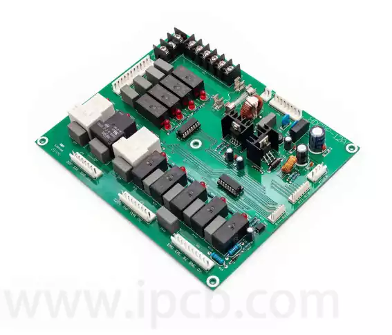
Through-hole connectors are one of the oldest and most traditional types of pcb board pin connectors. As the name suggests, these connectors are inserted through holes drilled in the pcb, with the pins protruding from both sides. This design provides excellent mechanical stability and is ideal for applications where durability is critical.
Through-hole connectors offer a wide range of options in terms of pin count, shape and size to suit different circuit designs. They are commonly used in industrial equipment, automotive electronics, aerospace systems, and other applications that require rugged connections that can withstand harsh environments.
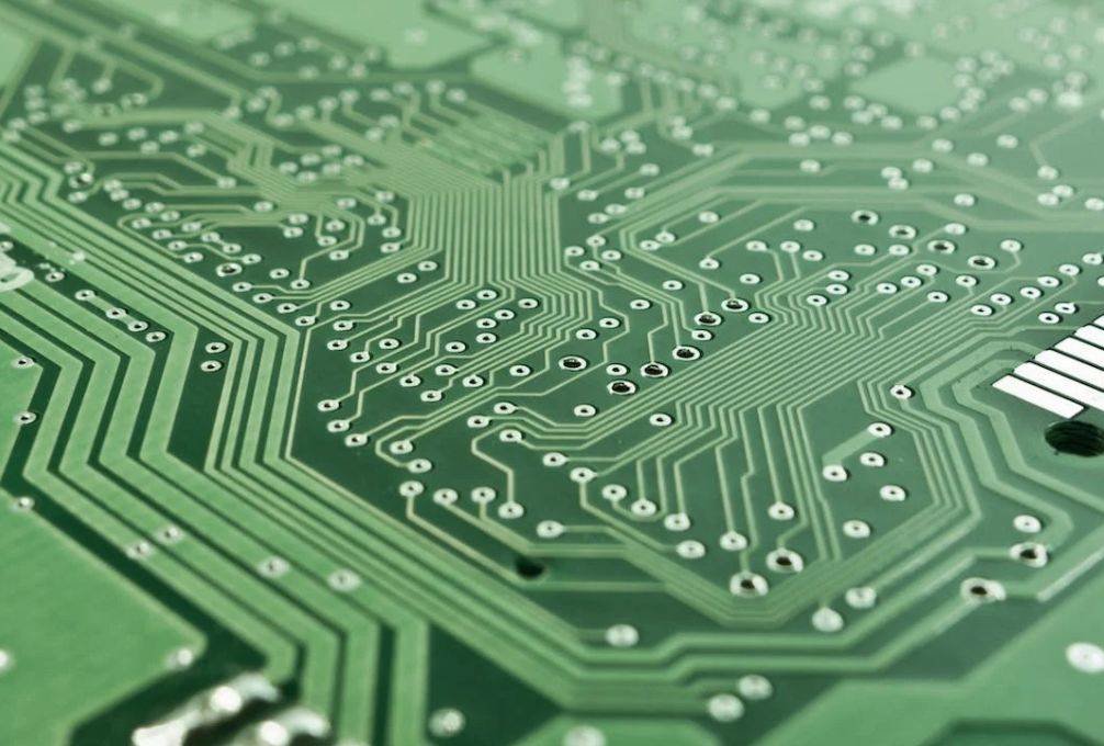
In recent years, surface mount connectors have gained popularity due to their space-saving design and ease of assembly. Unlike through-hole connectors, which require drilling holes in the PCB, surface mount connectors are soldered directly to the surface of the board using solder paste or reflow technology.
These connectors utilize small contact pads rather than pins, allowing for higher package densities on the pcb. Surface mount technology (SMT) has revolutionized electronics manufacturing by making electronic devices smaller, lighter and higher performing.
Surface mount connectors are a new breed of connectors that are connected to printed board circuits or microstrip circuits in a mounting manner, while the electrodes of pin-soldered connectors are located at the bottom of the connector and need to be soldered to the PCB pads through the pins, so the difference between surface mount connectors and pin-soldered connectors is mainly in the mounting method; surface mount connectors are directly mounted on the surface of the PCB, without drilling or changing the circuit board. The surface mount connector is directly mounted on the surface of the PCB without drilling or changing the circuit board, suitable for miniaturization and lightweight electronic equipment; while the pin-soldered connector needs to be pre-drilled holes or placed on the PCB pads, and then inserted into the pins into the solder holes or soldering pads, suitable for occasions that require a higher current or signal transmission.
Surface mount type connectors:
The electrodes of this type of connector are located directly on the surface of the connector, which can be directly mounted on the surface of the PCB and connected to the circuit or component on the PCB through soldering. Its installation process does not require piercing or alteration of the circuit board, thus reducing installation time and cost. Surface mount connectors have the advantages of low height, small size, light weight and high reliability, and are suitable for miniaturized and lightweight electronic devices, high-density assembly and automated production scenarios.
Generally speaking, the reliability of surface mount connectors is higher because they are directly mounted on the PCB, forming an integral part with the PCB, which reduces thermal stress and stress concentration due to soldering. In addition, the structure of surface mount connectors is more compact, which reduces the loss and interference in the signal transmission process.
Pin soldering type connector:
The electrode of this type of connector is located at the bottom of the connector and needs to be soldered to the pad of the pcb through the pins. The pins can be pins, fork fingers or other shapes to suit different installation needs. The installation process of pin-soldered connectors requires pre-drilling holes or placing pads on the pcb, then inserting the pins of the connector into the solder holes or pads, and then connecting to the circuit or components on the pcb through soldering. This type of connector is suitable for applications that require higher current or signal transmission, such as power supplies, audio equipment, etc.
The reliability of pin-soldered connectors is affected by a variety of factors, such as soldering quality, material selection, structural design and use of the environment, its reliability, stability and durability are also widely recognized and have a wide range of applications in various fields, such as audio equipment, sensor actuators, medical equipment, aerospace and automotive electronics.
In general, these two types of pcb solder pins connector reliability depends mainly on the actual application and environmental conditions, rather than simply the type of connector, even though the price of the surface mount type connector may be slightly higher than the pin solder type connector, because the surface mount type connector manufacturing process and material requirements are higher, at the same time the surface mount type connector production automation is higher, which can reduce the cost of labor and Production cycle, but the choice of which connector to use needs to be analyzed on a case-by-case basis, should be based on specific application scenarios and needs for comprehensive consideration in order to determine the best connection scheme.