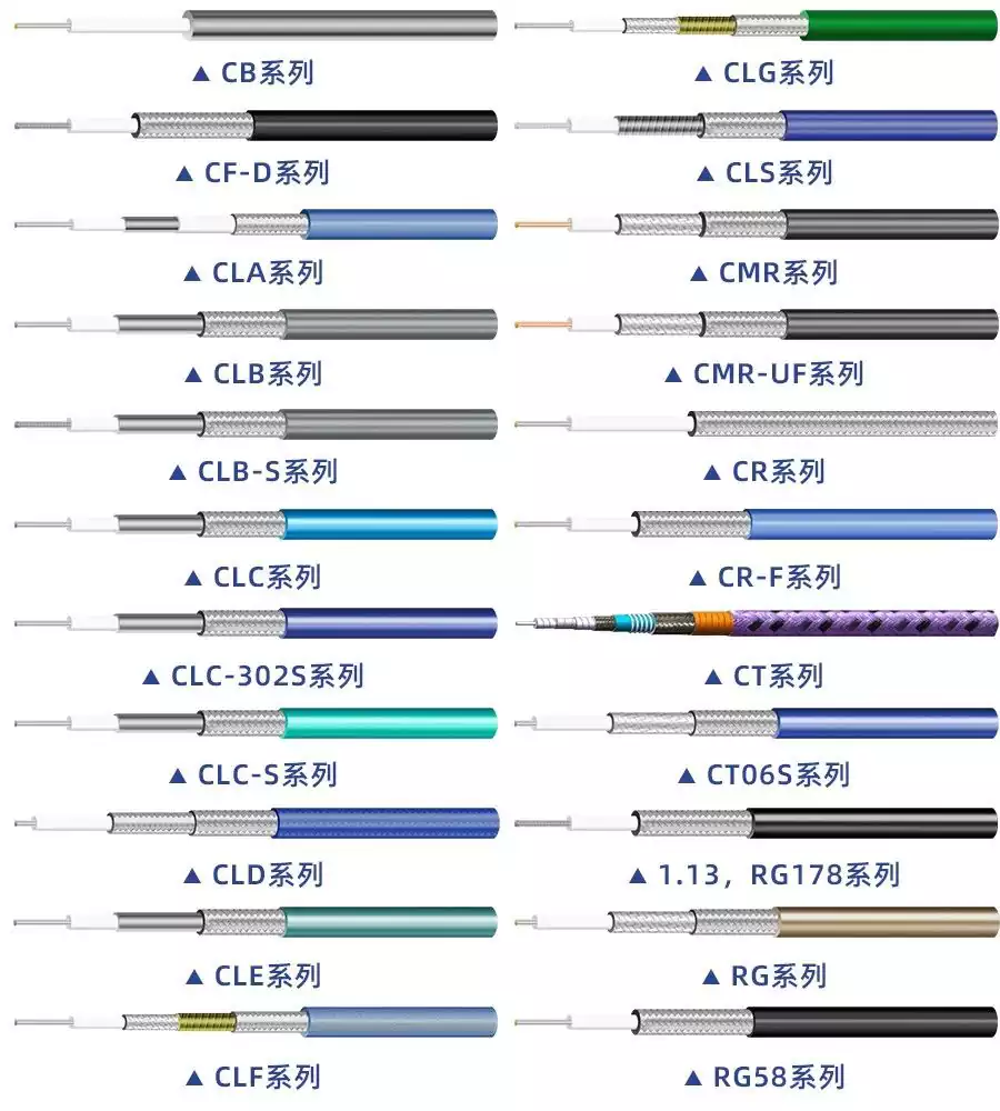
RF cable assembly is cable that transmit radio frequency (RF) signals from one device to another. They consist of coaxial cable and RF connectors at both ends. Coaxial cable has a central conductor surrounded by an insulating layer and a shielded outer conductor. RF connectors are designed to match the impedance and frequency range of the cable and the device.
Key Parameters in RF Cable Testing
Key Parameters in RF cable Testing The quality of the cable is critical for testing applications, as it ensures consistent and repeatable test results and maintains long-term reliable electrical performance.
Therefore, the rf cable assembly must be durable, capable of withstanding frequent movement, bending, and exposure to various environmental conditions, while maintaining reliable electrical performance.
- Electrical Performance Metrics
Electrical performance metrics are the first consideration. Generally, the higher the frequency, the higher the performance requirements for the cable. The following are key metrics:
① Voltage Standing Wave Ratio (VSWR) The closer VSWR is to 1, the better. Higher return loss indicates higher test system accuracy.
VSWR stability: Whether the VSWR curve remains stable and does not drift during cable vibration or bending directly determines the consistency of the tested device’s performance.
② Mechanical phase stability and mechanical amplitude stability
This primarily refers to changes in the electrical length and insertion loss of the cable assembly under specified mechanical bending or twisting conditions.
③ Insertion loss
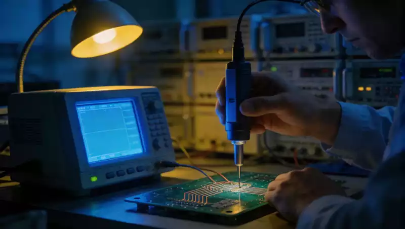
The insertion loss of the test cable can be calibrated at the vector network analyzer port and is not a critical parameter affecting the testing process.
The insertion loss of a test cable is primarily composed of three components: connector loss, cable loss, and loss caused by impedance mismatch.
- Mechanical and Physical Properties Proper usage methods can significantly extend the service life of a test cable. When using the rf cable, ensure proper protection and avoid cuts, scratches, or bending that could damage the cable. The following are important indicators:
① Flexibility
Test cables have relatively high requirements for flexibility. Flexibility is not solely determined by the sheath material; differences in the structure of the inner conductor, insulation layer, outer conductor, and sheath material also affect cable flexibility.
② Holding Force (Longitudinal Tensile Strength)
During use, test cables are prone to being pulled, twisted, or broken, often resulting in cable fractures or fractures at the connector interface. Many such issues stem from improper use. Test cables with good holding force typically feature high-quality braided layer materials and optimised connector structure designs.
③ Number of Bends
The number of bends a cable can withstand is directly related to its structure and material quality. If a cable has poor repeated bending performance, it can lead to centre conductor breakage and deformation of the braided wires.

RF cable transmission distance
Generally speaking, the higher the signal frequency, the greater the attenuation. Video signals have a large bandwidth, reaching 6 MHz, and the colour components of the image are modulated at the high-frequency end. As a result, when video signals are transmitted through coaxial cables, not only does the overall signal amplitude experience attenuation, but the attenuation of different frequency components varies significantly, with the colour components experiencing the greatest attenuation. Therefore, RF cables are only suitable for short-distance transmission of video signals. When the transmission distance reaches approximately 200 metres, the video quality will deteriorate significantly, especially with colours becoming dull and distorted.
In practical engineering applications, coaxial amplifiers are used to extend the transmission distance. Coaxial amplifiers amplify video signals to a certain extent and can also compensate for different frequency components through equalisation adjustments, thereby minimising distortion in the video signals output at the receiving end. However, coaxial amplifiers cannot be cascaded indefinitely. In a point-to-point system, coaxial amplifiers can typically be cascaded no more than two or three times; otherwise, video transmission quality cannot be guaranteed, and adjustments become difficult. Therefore, when using RF cables in surveillance systems, to ensure good image quality, the transmission distance is generally limited to around 400 to 500 metres.
The performance of RF cable assemblies is influenced by a combination of electrical and mechanical parameters, and the transmission distance is limited by signal attenuation. A thorough understanding of these characteristics, combined with reasonable selection and maintenance based on actual requirements, is key to ensuring high-frequency signal transmission quality and system reliability.


