Potentiometer circuit board is circuit boards that incorporate a potentiometer, an electronic component designed to regulate and control voltage or current in a circuit. Such circuit boards are commonly used in audio equipment, lighting regulation, instrumentation, and industrial controls for precise adjustment of equipment performance.
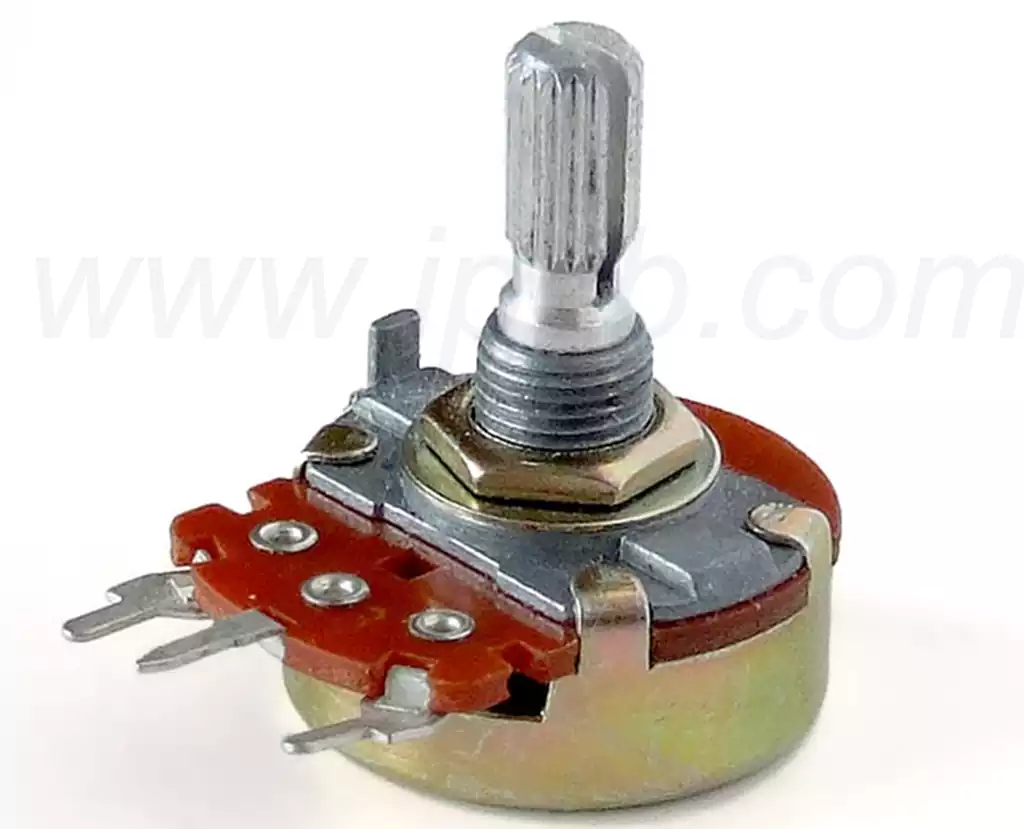
A potentiometer usually consists of three terminals, two of which are fixed and one of which is a movable sliding contact. As the sliding contact moves across the resistor body, the resistance of the potentiometer changes, thereby changing the output voltage. Potentiometers can be linear or logarithmic, the choice depending on the application requirements.
Basic Structure of Potentiometers
A potentiometer usually consists of a resistor body, sliding contacts and three leads (two fixed and one adjustable). The fixed terminals are the nominal resistance value of the potentiometer, while the adjustable terminal adjusts the resistance value by moving the distance between the sliding contacts and the fixed contacts. This structure allows the potentiometer to function as a variable resistor in a circuit and is suitable for a variety of application scenarios.
Operating Principle
The operating principle of a potentiometer is based on adjusting the output voltage or resistance value by rotating or sliding the contact to change its contact length on the resistor body. Specifically, when voltage is applied to the two fixed terminals of the resistor body, the movement of the sliding contact causes a change in the resistance value between the output terminals and the fixed terminals, and this change directly affects the voltage and current in the circuit.
Applications of Potentiometers
Potentiometers are widely used in a variety of electronic devices such as volume adjusters, brightness adjusters and as control elements for regulating input devices. By varying the output voltage, potentiometers enable fine regulation of devices, which is essential for the accurate use of audio and video equipment as well as measuring instruments.
How Potentiometers are Connected
When wiring a potentiometer, one of the fixed terminals is connected to the input voltage, the center terminal is connected to the output, and the rest of the terminals are grounded or suspended. This type of connection allows the user to easily obtain the desired voltage value and to control the circuit as required.
Precautions
When using potentiometers, attention should be paid to their load capacity and power rating to avoid damage to the potentiometers due to overloading. In the actual wiring, it should be ensured that the contact of the potentiometer is good in order to avoid signal fluctuation caused by poor contact during use. Ensuring smooth contact between the sliding contacts and the resistor body is critical to the performance of the potentiometer.
Key Strategies for Designing Potentiometer circuit board
- Selecting the right type and size of potentiometer
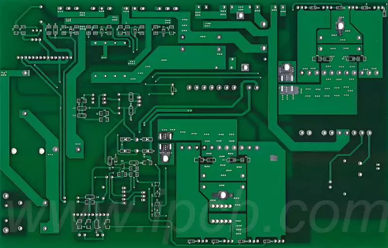
Selecting the right type and size of potentiometer requires consideration of several factors, including resistance value, power rating, and application requirements. For general purpose applications, carbon film potentiometers can be selected, while for precision applications, wirewound potentiometers may be required. In addition, the type of adjustment (rotary or sliding), linearity characteristics (linear or logarithmic), and environmental conditions need to be evaluated to ensure optimum performance in a given circuit. - Planning the Layout on the BoardWhen planning the layout of the potentiometers on the board, it is important to ensure that the potentiometers are easy to access and it is recommended that they are placed at the edges of the board.
The layout should take into account signal integrity,avoid interference with high-voltage components, and ensure that adjustable components are located away from heat sources.In addition,the spacing between the potentiometer and other electronic components should be reasonably arranged to minimize contact interference. - Design the electrical connection
Potentiometers usually have three terminals:two terminals connected to power and ground,and one movable terminal for output voltage adjustment. When used as a voltage divider,the adjustable output voltage is obtained from the center terminal and the outer terminal is connected to the power supply and ground. Proper connection design ensures good contact and avoids damage caused by excessive current. - Add decoupling capacitors to improve stability
In order to improve the stability of the potentiometer, adding decoupling capacitors is very important.These capacitors can filter high-frequency noise and provide a stable power supply by acting as a local energy memory,thus reducing coupling interference between pcb components.Also, placing decoupling capacitors as close to the potentiometer as possible can further improve response during transient current demands. - Test potentiometer performance and stability
Measure the resistance of the potentiometer circuit board to ensure that it meets specifications and operates smoothly.Key tests include checking the smooth movement of the adjustment knob, verifying the quality of the electrical contact between the sliding arm and the resistive element,and evaluating the consistency of the resistance value in daily use. Fluctuating readings may indicate degradation of performance and require periodic inspection. - Optimize Design to Ensure Best Performance
Optimizing potentiometer circuit board design is critical to ensuring reliable performance of electronic circuits.Key design factors include selecting the right type of potentiometer, carefully choosing resistance and power ratings,and ensuring proper connections to minimize the effects of contact resistance and thermal variations. Also, electrical parameters such as power ratings and noise characteristics are evaluated to enhance stability and accuracy in applications such as audio and optical control.
Potentiometer circuit board is key electronic components that regulate the voltage and current in a circuit by changing the resistance value. Its wide range of applications cover areas such as volume control, brightness adjustment and gain control. Understanding the basic structure and working principle of potentiometers can help optimize circuit design and enhance device performance.