Printed circuit boards are the bearers of electronic components, which provide a master for connecting the various components in a circuit. Structurally, PCBs are mainly classified into single-sided, double-sided and multilayer boards.
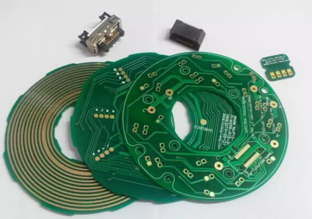
The parts and wires of a single panel are concentrated on each side of the substrate. This type of printed circuit board is called a single panel because it has wiring on only one side. Since the wiring cannot cross each other and must follow strict winding rules, this type of board is mainly used for early circuit design. Its wiring diagrams are usually done using screen-printing techniques by printing resist on the copper surface, etching and punching.
A double-layer printed circuit board, also called a double-sided pcb board, is a circuit board with conductive wiring on both sides. Its manufacture requires two copperisation (etching) processes, making it relatively difficult and expensive to produce.
Double-sided printed circuit boards are designed as printed circuit boards with copper on both its top and bottom layers. This type of PCB circuit board can be wired and soldered on both sides, separated by an insulating layer, and is one of the most commonly used printed circuit boards. The double-sided board design greatly reduces the complexity of wiring, and is therefore widely used in a variety of circuit designs.
To make full use of the wires on both sides of a double-sided printed circuit board, it is necessary to create proper circuit connections between the two sides. This allows the designer to freely route wires on both sides of the board, thus greatly increasing the flexibility and efficiency of the design. This ‘bridge’ between the two sides is called a vias. On a PCB circuit board, it is a small hole filled or coated with metal that connects to the wires on both sides. Because a double-sided board is twice the size of a single-sided board, it solves the problem of staggered wiring in a single-sided board by allowing free conduction between the two sides through the vias. This makes double-sided boards ideal for more complex circuit designs.
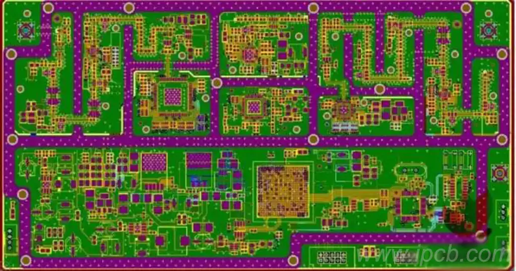
Multilayer pcb boards are printed circuit boards with three or more layers, i.e. like a sandwich cake, with a core layer and an inner layer in the middle of the printed circuit board. Multilayer pcb boards can be categorised as 4-layer boards, 6-layer boards, 8-layer boards, 10-layer boards, etc. Multilayer pcb boards have a complex production process and relatively high manufacturing costs, but they have the advantages of more stable lines, enhanced interference immunity, higher signal-to-noise ratios, smaller areas, and lower costs.
The main difference between single-layer, double-layer and multi-layer PCB circuit boards is the number and complexity of their conductive layers.
Single-layer PCBs are the most basic type of printed circuit board with only one conductive layer. As all components and connections must be concentrated on the same side, wiring design is more restricted, suitable for simple structure, lower cost of electronic products, such as remote control and LED lights.
Dual-layer PCBs have two conductive layers, top and bottom, and interlayer connections are realised through vias, allowing for a significant increase in wiring flexibility. Dual-layer PCBs are widely used in common electronic devices such as mobile phones, TVs and computers due to their better design flexibility and wide range of applications.
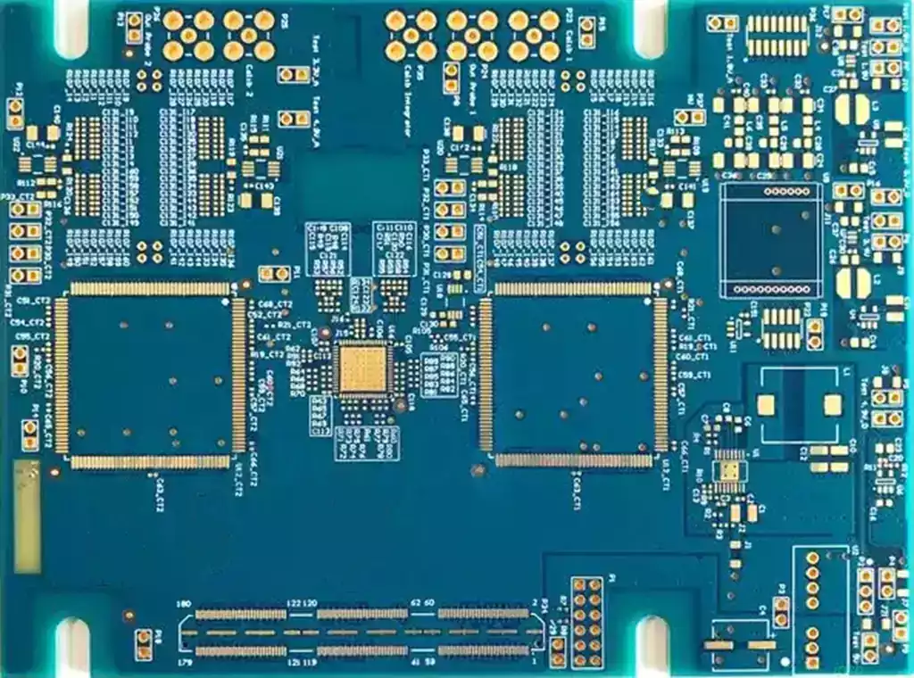
Multilayer PCB board, on the other hand, contains three or more conductive layers, which are connected to each other through intermediate vias between multiple layers to support higher density component layout and complex circuit design. It is widely used in communication equipment, servers and industrial control equipment, while allowing circuits to be stacked vertically to increase integration, reduce size and improve EMI performance. High-frequency PCBs are designed for signal transmission at frequencies exceeding 1 GHz, and are usually made of FR4 glass-fibre epoxy resin boards, polyphenylene ether (PPO) and polytetrafluoroethylene. The design takes into account dielectric constants, dissipation factors, losses and dielectric thicknesses, etc., in order to ensure the quality and integrity of signal transmission.
Single-side, double-side and multilayer pcb boards each have different structural characteristics and scope of application, to meet the needs of different electronic products on circuit complexity and performance. With the development of electronic equipment to high-performance, miniaturised direction, multi-layer PCB circuit board with its high integration and excellent electromagnetic compatibility performance, is gradually becoming the mainstream choice. Understanding the difference between the various types of printed circuit board helps designers to choose the most appropriate type of board according to the specific application requirements, thus enhancing the overall performance and reliability of the product.