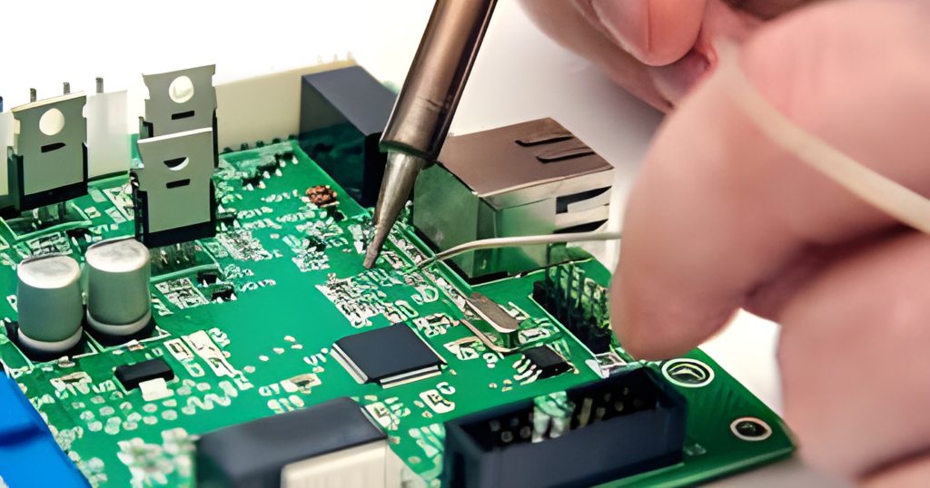
What is printed circuit board switches?Printed circuit board switches is an electronic component used to control circuit on/off, function selection, etc. It is one of the more common components on circuit boards. A switch consists of a single contact and a number of linked contacts, which can be operated to connect or disconnect multiple sets of polymerised contacts to control the switching of a circuit.
Why are printed circuit board switches so critical?
Although there are other types of electronic switches on the market, we strongly recommend prioritising PCB switches, and there is a good reason for this. The inherent conductivity of copper in printed circuit board switches facilitates the smooth flow of current with very low resistance.
Superior performance in a wide range of environments
These switches are suitable for outdoor applications. Their ability to withstand extreme conditions such as heat, humidity, and inclement weather makes them ideal for outdoor applications.
Customisation and adaptability
The most striking feature of printed circuit board switches is their ability to be used on any surface. They can be mounted on different materials, such as gold plate. You may find beautifully designed switches on gold plates that are both elegant and practical.
Optimised manufacturing processes
Thanks to the wide range of soldering techniques, printed circuit board switches are extremely easy to manufacture. This feature not only simplifies the production process, but also increases the efficiency of the switches. The reliability and consistency of the switches are ensured by the manufacturer through the use of these soldering techniques.
Types of switches on circuit boards:
Single-pole switches
Single-pole switches have only one contact. When the switch is open, the contact is connected to another contact, closing the circuit. When the switch is closed, the contact is disconnected from the contact and the circuit is broken. Single-pole switches are usually used in low-current, low-voltage circuits.
Bipolar Switches
A double-pole switch has two contacts that can control two circuits at the same time. When the switch is open, both contacts are disconnected and the circuit is broken. When the switch is closed, both contacts are closed and the circuit is connected. Bipolar switches are used in medium current, medium voltage circuits.
Pushbutton Switches
Pushbutton switches are available in both general and double pole types. Pushbutton switches operate by pressing the button, the switch closes; pressing the button again, the switch breaks. General pushbutton switches are used in low-current, low-voltage circuits, and bipolar pushbutton switches are used in medium-current, medium-voltage circuits.
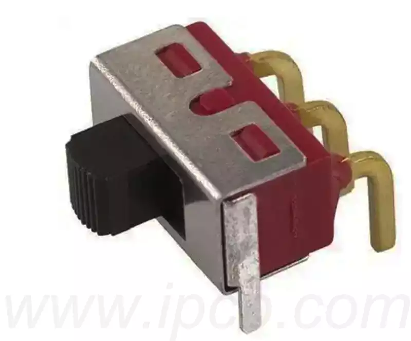
Toggle Switches
Toggle switches are usually available in single-pole and double-pole types. Toggle switches close and break the switch by manually rotating or toggling it. Single-pole toggle switches are used in low-current, low-voltage circuits, and double-pole toggle switches are used in medium-current, medium-voltage circuits.
Rotary Switches
Rotary switches are used when multiple circuits need to be controlled. Rotary switches can be rotated to change the state of connection of the contacts, thus controlling the opening and closing of the circuit. Rotary switches are typically used in medium current, medium voltage circuits.
Printed circuit board switches are used in a variety of applications
Consumer electronics: Widely used in smart phones, cameras and audio equipment.
Household appliance industry: An important part of the user interaction interface of all kinds of home appliances.
Smart home system: Deeply integrated into smart thermostats, lighting systems and home automation control platforms.
Wearable devices: Provide core support for the control of smart watches, sports bracelets and other devices.
Gaming device market: realising human-computer interaction functions through game controllers and other terminals.
Automotive electronics industry: Covering the whole car electronic system from instrument control to electric window adjustment.
Medical equipment field: as the key function realisation carrier of medical testing and treatment equipment.
Aerospace industry: critical to the stable operation of avionics and flight control systems.
Audio system field: applied to power amplifiers, mixing consoles and professional audio control equipment.
Printed circuit board switches circuit design
- The design process from schematic to PCB establishes component parameters ->: Input schematic netlist ->: Set design parameters ->: Manual layout ->: Manual wiring ->: Verify design ->: Audit ->: CAM output.
2.Parameter Setting The spacing between adjacent wires must meet electrical safety requirements, and the spacing should be as wide as possible to facilitate operation and production. The minimum spacing should be at least suitable for withstand voltage. When the wiring density is low, the spacing of signal lines can be increased appropriately. For signal lines with inconsistent high and low levels, the spacing should be as short as possible and increased. In general, the wiring spacing is set to 8 mils. The distance from the edge of the hole inside the pad to the edge of the printed circuit board should be greater than 1mm to avoid defects in the pad during processing. When the pad is connected to the wiring is thin, the connection between the pad and the wiring should be designed in the shape of a teardrop, which has the advantage that the pad is not easy to peel off, but the wiring and pad is not easy to disconnect. - Component layout practice has proved that even if the circuit schematic design is correct, improper design of the printed circuit board, the reliability of electronic equipment will be adversely affected. For example, if two thin parallel lines of a printed circuit board are placed against each other, a delay in the signal waveform is formed and reflected noise is formed at the termination of the transmission line.
In printed circuit board switches design, there are several key design principles and considerations that need to be adhered to in order to ensure circuit stability and performance.
Component Layout
Layout should take into account the physical dimensions of the board. A board that is too large will result in increased impedance and reduced noise immunity, while a board that is too small will dissipate heat poorly. The recommended board shape is rectangular with an aspect ratio between 3:2 or 4:3.
The layout of components should be based on the principle of facilitating signal flow and reducing signal loss, and the power components should be evenly, neatly and compactly arranged.
For high-frequency circuits, the distribution parameters of components should be considered, and components should be arranged in parallel as far as possible to reduce magnetic field interference.
Wiring design
The spacing of adjacent wires should be able to meet the electrical safety requirements and usually withstand at least the corresponding voltage. In the case of low wiring density, the spacing of signal lines can be increased appropriately.
All printed wires passing AC currents should be designed to be as short and wide as possible to minimise the effects of their inductance and impedance.
During wiring, corners at 90 degree angles should be avoided to minimise signal reflection and attenuation.
Grounding and Power Design
The grounding design should follow the principle of single-point grounding to reduce the loop current and interference formed by the ground. For high current circuits, an earth wire as wide and short as possible should be used.
The width of the power and earth wires should be appropriately widened to reduce loop resistance and improve noise immunity.
Inspection and Verification
After completing the wiring design, all distances between alignments, pads and through holes should be carefully checked for reasonableness to ensure that the requirements of the production process are met.
Conduct a review of the design rules, including layer definitions, line widths, spacing, pad and via hole settings, to ensure compliance with the design requirements.
Printed circuit board switches have become a key part of the electronics field due to their unique advantages and multiple applications. With scientific design principles, their performance can be fully utilised.