What is Rigid-Flex Circuitry?
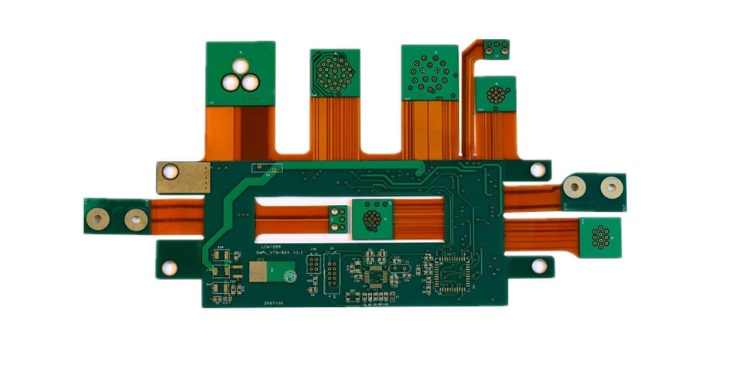
The birth and development of FPCs and PCBs has given rise to the existence of rigid flex pcb manufacturers. Rigid-Flex PCB technology has its origins in the military, where space saving and reliability are top priorities. This dates back to the 1980s. Today, the rigid-flex PCB market encompasses many areas from consumer electronics to medical devices. Rigid-flex PCBs, therefore, are flexible circuit boards and rigid circuit boards, which are combined together after press-fit and other processes according to the relevant process requirements to form a circuit board with FPC characteristics and PCB characteristics.
Rigid-flex PCB is a combination of rigid and flexible circuit board design, usually used in applications that require both high strength and flexibility. It combines a rigid PCB with a flexible PCB for more complex electrical connections and structural layouts. Such a design improves the durability and adaptability of the equipment, and especially excels in environments where space is limited or dynamic movement is required.
Key benefits of rigid-flex PCBs include:
Space saving: The ability to bend or fold in certain areas allows rigid-flex PCBs to be compressed into much smaller sizes than rigid PCBs, creating more space for components and other features in electrical equipment.
Reduced Weight: Because rigid-flex PCBs are much smaller than solid boards, they are also lighter in weight. This reduces the overall weight of the device, favoring applications such as medical implants and wearable electronics.
Easier assembly: Rigid-flex boards are easy to assemble because they use fewer components. They also require simpler installation steps because you don’t need a lot of connectors or cables to connect circuits.
Improved reliability: The fact that you don’t need many cables or connectors (fewer solder joints) when using rigid-flex PCBs improves the overall reliability of electrical equipment.
The main disadvantages of rigid-flex PCBs include:
Rigid-flex PCBs are more expensive and have a longer production cycle due to the many production processes, difficulty in production, lower yields, and more material and labor invested.
Rigid-Flexible PCB Materials
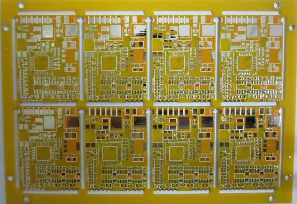
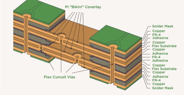
Rigid-flexible PCB materials include materials for making rigid PCBs and materials for making flexible PCBs. The rigid part of the board is usually made of materials such as FR4, or glass fiber reinforced with epoxy resin, known for its durability and strength.
For the flexible part of the board, polyimide is the most common material, mainly due to its good flexibility and better thermal properties. Depending on the specific application of the board, other materials can also be used.
For alignments, both in flexible and rigid components, copper is the most commonly used material for rigid flex pcb manufacturers. Copper traces in flexible parts must bend without problems and are often made of rolled annealed copper.
Flexible PCB Design Flow
The design and layout of flexible and rigid-flex PCBs are interrelated; the main difference between flexible and rigid-flex is an interconnect that spans to the rigid end of the board. Just like a standard rigid PCB, the flex design flow begins with designing the stackup structure, placing components, planning and routing paths, and finally cleaning up the layout in preparation for fabrication. To ensure that the flex section has the desired mechanical properties, some additional steps are required, such as adding reinforcement tabs, selecting an overlay or photoimageable solder paste shielding material, or setting up a static bend in the design.
Because the flex tape design process is heavily focused on the stackup design and its integration with any rigid sections, the stackup design is a critical part of the flex/rigid-flex composite PCB design process. In addition, factors like copper weight and component/wiring density in certain board areas can limit flexibility, making rigid-flex composite boards more favorable. To get started with a flex or rigid-flex composite design, consider the following aspects of the final assembly and how the design will be integrated into its enclosure:
Floorplanning: Where does the flex tape need to be bent in the PCBA and how will the design be mounted into its enclosure? Bending and mounting areas need to avoid components, and you may want to use rigid sections for certain high pin count ICs or high density circuit areas. Decide where the flex tape will be located relative to areas of the board with high component counts.
Number of Layers: How many layers are needed for routing and do some of these layers need to be used in the rigid section? If there is a rigid section, the flex tape will need to be mounted in the center of the stack, which can make routing difficult where more planar layers are required (e.g., in high-speed designs).
Rigidity: Can you accept a stiffer board or do you need a highly flexible assembly? This can be achieved by controlling component density, copper thickness, or by adding reinforcement sheets to certain parts of the flexible tape. If you need very stiff polyimide sections, it may be worthwhile to just use completely rigid sections. Reinforcement tabs can be used to support higher component densities on the flex tape, and they will cost less than integrating a rigid section.
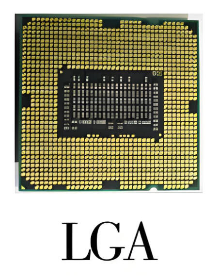
High pin density components: Smaller SMD components, such as passive components, can be easily placed on polyimide flex tape. Other components in BGA packages require a more advanced through-hole structure and more inner layers to support the wiring. For high-speed or RF designs, skeletonized planar layers may be required to provide the required impedance or ground continuity (e.g., for single-ended signals), as well as isolation.
The needs of your application may require a balance between many requirements. At the same time, rigid-flex PCB manufacturers need to ensure that their rigid-flex or flexible designs are manufacturable and will be reliable in real-world applications.
Benefits of Flexible PCBs and Rigid-Flex Hybrid PCB Designs
For those inexperienced in flexible circuit design, let’s look at some of the key benefits that drive designers to use flexible materials. While some specific design considerations are required to ensure that a flexible or rigid-flex hybrid PCB design is manufacturable as intended, these designs offer many benefits not seen in rigid circuit boards.
Space and Weight: Many of today’s electronic designs face the challenge of reducing the size and weight of the final product. Flexible materials can replace more bulky wires and soldered connections, and oft-cited statistics show that this savings can be as high as 60% under the right circumstances. That’s pretty significant.
Packaging Advantage: There’s no denying that the ability to bend and fold flexible circuits around corners and provide triaxial connections gives PCB designers significant advantages over traditional wires and cables and rigid printed circuit board materials. In fact, the ability to maximize these advantages is limited more by imagination than anything else.
Simplified Assembly: A simple flexible circuit can drastically shorten assembly efforts compared to bulky wires and cables. A single flexible circuit can replace multiple items on the bill of materials.
Thermal Management: Polyimide materials can withstand high heat applications, and thin polyimides dissipate heat more efficiently than thicker, less thermally conductive materials, making them the preferred choice for high-power, high-frequency designs.
Biocompatibility: Polyimide and LCP are two flexible materials that are excellent choices for biocompatibility and are often used in medical and wearable applications as a result. Interestingly, I’m finding more and more interest in flexible circuits that use gold as a conductor rather than copper, providing a fully biocompatible option.
What are the different types of rigid-flexible PCB prototypes?
Visual Model
The Visual Model Rigid Flex PCB Prototype helps you design and interactively demonstrate your new electronic product.
A visual model is the best way to visually explain the idea behind a concept.
You can use this prototype to present your design to potential investors or customers.
It plays an indispensable role in the early stages of rigid-flexible PCB design work.
Proof of Concept Prototype
This is a physical model of a component that you can create to verify space requirements before building an expensive prototype.
You can use a proof-of-concept Rigid-Flex PCB prototype for design verification, testing of digital and analog electronics and circuits.
Working Prototypes
You can assemble working prototypes to meet customer-specific design requirements.
The final PCB product therefore demonstrates the features and functionality of the end product.
You can test the design functionality of a prototype and determine whether it can be successfully made into a final product.
This flexible electronics assembly technology speeds your time to market by eliminating costly delays due to engineering changes!
Functional Prototypes
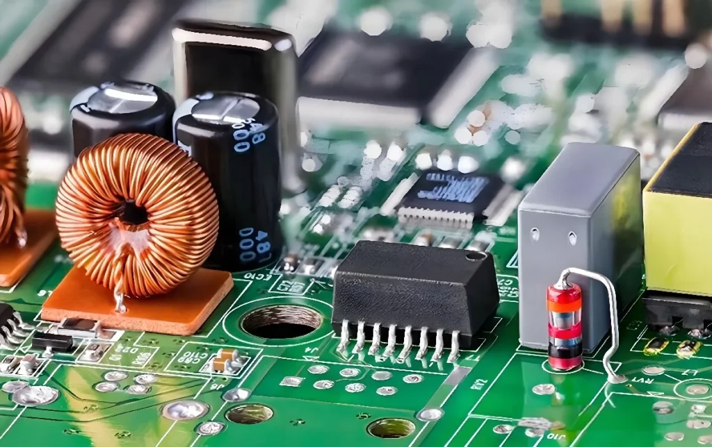
You can use Functional Rigid-Flex PCB prototypes for short-run production, and manufacturers can also source this type of cost-effective PCB prototype. They can be used to fit different components well, especially IC chips, resistors, capacitors, and other parts with fine spacing and small loads.
Rigid-Flex PCB Applications
Rigid-Flex PCB applications span many industries, and they offer the best of both worlds – the strength and durability of rigid PCBs, and the flexibility and space-saving features of flexible PCBs. Common uses for rigid-flex PCBs include the following listings
Automotive and Industrial Electronics: One of the most popular applications for rigid-flex PCBs is in the automotive and industrial sectors, where they provide robust and reliable performance for demanding applications. Examples include actuators in industrial systems and robots.
Medical Devices: Rigid-Flex PCBs have been successfully used in medical implants that require electrical connections to power different functions. Their flexibility and reliability make them ideal for such applications.
Wearable Electronics: In wearable electronics, rigid-flex PCBs offer the best of both worlds – strength to support components and flexibility to adapt to different shapes or sizes. Examples include fitness trackers, smartwatches and other devices that require flexible circuitry.
Military Electronics: Rigid-flex PCBs have been used in a wide range of military electronics, from aircraft avionics to communications systems. Their ability to remain rigid when needed and bend when necessary gives them an advantage over rigid or flexible PCBs.
Rigid-Flex PCB Manufacturers Capabilities
Does your existing preferred manufacturer routinely handle flexible materials? Does the complexity of your design match the preferred manufacturer’s capabilities, or are you outside their area of expertise? This is certainly not a comprehensive list of everything to consider, but is intended to start the thought process of considering designing with flexible circuits. Your PCB manufacturer will be a great resource and you should contact them to come up with an expected stacking sequence to ensure it can be reliably manufactured. They understand the materials and manufacturing process and are always happy to help guide their clients through the process of learning about flexible PCBs.
Conclusion
For applications that require flexible electronics in specific areas but without sacrificing the strength of a rigid board for the rest of the board, the presence of a rigid flex pcb manufacturers solves a major problem. They offer many advantages over standard rigid or flexible PCBs, such as cost and space savings as well as weight reduction and increased reliability.