Rogers 5880 PCB Introduction and Material Properties
Rogers 5880 PCB is a highly regarded specialty circuit board material for high-frequency and high-speed electronic designs. It belongs to Rogers’ family of high-performance fluorinated polymer substrates. Compared to traditional FR-4 or CEM-1 materials, Rogers 5880 offers significant advantages in dielectric constant, dissipation factor, and temperature stability, enabling it to deliver exceptional performance in RF, microwave communications, antenna design, and high-speed digital circuits. A key characteristic of this substrate is its extremely low dielectric loss factor (Df), typically around 0.0009 to 0.0012 (10 GHz). This significantly reduces energy attenuation during high-frequency signal transmission, thereby maintaining signal integrity and high transmission rates.
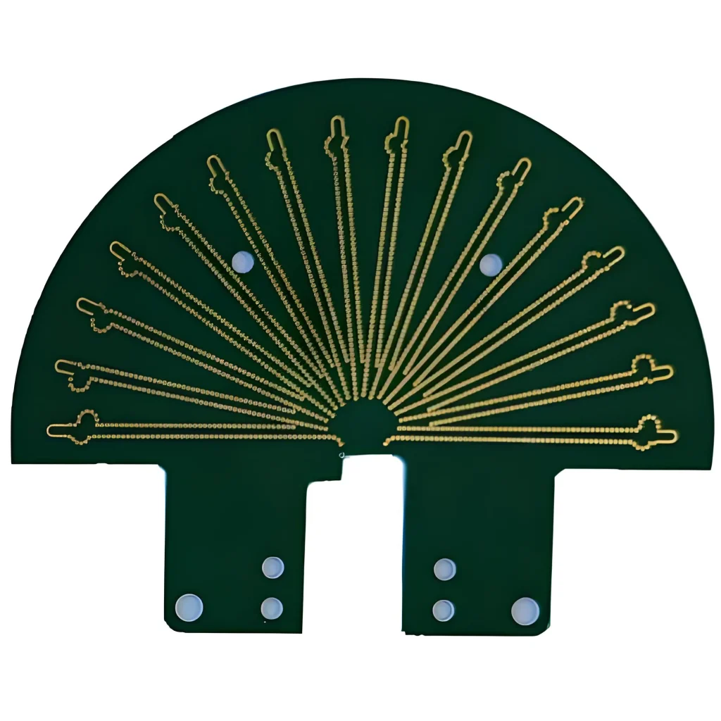
Another key feature of Rogers 5880 PCB is its stable dielectric constant (Dk), typically around 2.2, with minimal temperature variation. This property is crucial for high-speed microwave and millimeter-wave circuits, as signal transmission delay, impedance matching, and reflection loss are all directly related to the Df. Even in operating environments ranging from -50°C to +150°C, the Rogers 5880 substrate maintains relatively constant electrical performance, ensuring stable operation of RF modules and high-speed digital systems.
From a material structure perspective, the Rogers 5880 PCB is constructed from a composite of polytetrafluoroethylene (PTFE) and glass fiber reinforcement. This structure combines the low dielectric loss characteristics of PTFE with the mechanical strength of glass fiber. Compared to pure PTFE sheets, reinforced Rogers 5880 offers advantages in dimensional stability and manufacturability, making it suitable for precision machining, drilling, and etching processes in PCB manufacturing. Furthermore, its low coefficient of thermal expansion (CTE typically around 16 ppm/°C) results in lower interlayer stress during multilayer board stacking, preventing warping or cracking of high-frequency boards during soldering or thermal cycling.
In terms of electrical performance, the Rogers 5880 PCB not only features low loss and a stable dielectric constant but also excellent insulation strength and arc resistance. These characteristics ensure that the circuit board can withstand transient high voltages and pulsed currents without breakdown or partial discharge in high-power microwave signal transmission or RF amplifier applications. Furthermore, the high surface flatness of the 5880 substrate facilitates fine wiring and high-density interconnects, offering significant advantages for the design of millimeter-wave antennas and high-speed signal channels.
From a manufacturing perspective, the Rogers 5880 PCB places high demands on manufacturing equipment and processes. Due to the flexibility and low surface energy of its PTFE matrix, traditional screen printing, etching, and drilling methods require process optimization; otherwise, copper layer peeling or hole wall burrs may occur. Modern PCB manufacturing typically employs techniques such as laser drilling, plasma cleaning, and surface chemical treatments to ensure the accuracy of the circuit pattern and the reliability of vias. Simultaneously, the multilayer 5880 PCB stack-up process requires strict control of temperature, pressure, and lamination time to guarantee the geometric accuracy and electrical performance consistency of the multilayer board.
In summary, Rogers 5880 PCB, with its low dielectric loss, stable dielectric constant, excellent mechanical properties, and high-temperature adaptability, has become the material of choice for high-frequency and high-speed electronic design. It not only ensures signal integrity and high-speed transmission, but also provides a reliable physical and electrical foundation for complex multilayer circuits. These characteristics provide a solid foundation for the design of RF communications, radar, antennas, and high-speed digital systems, making it an indispensable foundational material for modern high-performance electronic systems.
Manufacturing Process and Key Technologies for Rogers 5880 PCBs
The manufacturing of Rogers 5880 PCBs differs significantly from that of ordinary FR-4 circuit boards. Its material properties necessitate more precise process control and specialized equipment. Because Rogers 5880 utilizes a polytetrafluoroethylene (PTFE) composite substrate, while offering extremely low dielectric loss, its softness and chemical inertness present significant technical challenges in machining, metallization, and lamination. Achieving high-frequency performance depends not only on the material itself but also on the precision and consistency of the entire manufacturing process.
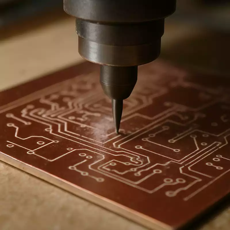
During the drilling and metallization stages, PTFE is prone to burrs, hole wall tears, and residual material within the hole, necessitating the use of specialized drill bits and high-speed drilling processes. Unlike FR-4, Rogers 5880 sheet material is typically frozen before drilling to temporarily increase the material’s hardness and improve the finish of the drilled hole edges. Plasma cleaning is also essential, removing organic residue from the hole and increasing the surface energy of the hole walls, ensuring good adhesion for the subsequent electroless copper plating. Only after these pre-treatment steps are complete can the reliability of the plated-through holes be guaranteed.
Surface treatment is another critical step. Due to the low surface energy of PTFE, the bond between the copper foil and the substrate is weak, necessitating plasma activation or chemical roughening to enhance adhesion. Common methods include using sodium-based activation solutions or fluorine plasma treatment to create a bondable microscopic roughness on the surface. Subsequently, the copper layer can be deposited on the substrate surface via electroplating or electroless plating, forming a strong metal-to-metal interface. This process directly impacts the accuracy and conductive properties of the subsequent etched pattern.
During the trace etching stage, the high-frequency characteristics of Rogers 5880 PCBs place extremely high demands on trace shape and edge smoothness. Any irregularities in the etched edges will cause deviations in characteristic impedance, thus compromising signal integrity. To ensure stable high-frequency signal transmission, manufacturers typically use precision exposure equipment and high-resolution dry film, combined with automated development and etching control systems, to ensure consistent trace geometry. Furthermore, for millimeter-wave applications, the design even requires consideration of the interaction between copper foil thickness and edge etching effects during the etch compensation stage to achieve ideal impedance control.
Lamination and multi-layer manufacturing processes are among the most challenging aspects of Rogers 5880 PCBs. Due to the difference in thermal expansion coefficient between 5880 substrate and other conventional materials, precise control of the temperature profile and pressure distribution during lamination is crucial to prevent bubbles, delamination, and warping between layers. Typical lamination temperatures are approximately 290°C to 310°C, with pressures controlled between 3 and 4 MPa, and sufficient cooling to ensure material crystallization stability. When stacking Rogers 5880 with other materials (such as FR-4 or Rogers 4003C), a compatible bonding film, such as Rogers 3001 or FEP film, is required to prevent delamination due to excessive interfacial stress.
During the soldering and assembly process, Rogers 5880 PCBs exhibit good thermal stability, but the temperature profile still requires strict control. Due to the relatively low thermal conductivity of PTFE, localized overheating can cause copper delamination or substrate warping. It is generally recommended to control the heating rate within 1.0-1.5°C per second during hot air reflow soldering and use a medium-temperature solder (such as Sn63Pb37 or lead-free SnAgCu alloy). Furthermore, to prevent component pad lift, surface plating such as ENIG (electroless nickel gold) or ENEPIG (electroless nickel palladium gold) can be used to ensure excellent solder wettability and oxidation resistance.
Quality inspection and reliability verification of Rogers 5880 PCBs are also essential. In addition to routine electrical continuity testing, X-ray inspection, and impedance control verification, high-temperature and high-humidity aging tests and thermal shock tests are required to evaluate the performance stability of the multilayer structure under extreme environments. For RF and microwave applications, a vector network analyzer (VNA) should also be used to test dielectric loss and insertion loss to verify that design targets are met.
In summary, manufacturing Rogers 5880 PCBs is a highly systematic engineering process involving knowledge from multiple fields such as materials science, precision machining, chemical surface treatment, and electrical performance control. Deviations in any process parameter can affect the final electrical performance; therefore, only manufacturers with mature experience in high-frequency board manufacturing can ensure the quality and consistency of such circuit boards. Rogers 5880 is not only a high-performance material but also a comprehensive test of manufacturing processes and engineering capabilities.
Main Application Areas and Advantages of Rogers 5880 PCBs
In today’s era of continuous development of high-frequency and high-speed electronic systems, Rogers 5880 PCBs have become a core foundational material in many key technology areas. Rogers 5880’s low dielectric constant, extremely low loss factor, and excellent thermal stability make it widely used in radio frequency (RF), microwave, radar, antenna systems, and high-speed digital communications. Compared to traditional FR-4 or ceramic substrates, Rogers 5880’s superior signal integrity and long-term reliability make it the preferred solution for design engineers seeking extreme performance.
In RF and microwave communication systems, Rogers 5880’s advantages are particularly pronounced. With a dielectric constant of only 2.2, signals are virtually unaffected by dielectric absorption during transmission, significantly reducing insertion and reflection losses. This means higher signal transmission efficiency and stable phase characteristics can be achieved in wireless communication base stations, radar front-end modules, and satellite communication transceiver units. Especially in the millimeter-wave band (30–300 GHz), Rogers 5880 maintains extremely low dielectric loss, which is crucial for 5G base station antennas, phased array radars, and high-speed millimeter-wave links.
In the aerospace and defense electronics fields, Rogers 5880 PCBs have been successfully applied to various high-reliability systems due to their excellent dimensional stability and environmental adaptability. For example, in airborne radars, satellite navigation modules, seeker antennas, and electronic warfare equipment, this material maintains excellent electrical performance despite extreme temperature fluctuations, vibration, and radiation. Compared to ceramic materials, Rogers 5880 offers advantages in weight and processing flexibility, significantly reducing system loads while meeting stringent RF performance requirements. The material’s low thermal expansion also effectively prevents mechanical stress from the aircraft’s high- and low-temperature cycles, improving long-term system stability.
In high-frequency antennas and power amplifier modules, Rogers 5880’s low dielectric constant facilitates more compact designs and higher radiation efficiency. For RF front-end circuits such as microstrip antennas, filters, and power dividers, 5880’s uniform dielectric properties ensure phase coherence of signals along the transmission line, optimizing antenna gain and directivity. Furthermore, using Rogers 5880 in high-power amplifiers (PAs) and low-noise amplifiers (LNAs) not only reduces signal loss but also effectively mitigates the risk of heat buildup in the circuits, ensuring stable operation of power devices under high-load conditions.
Rogers 5880 also demonstrates significant advantages in high-speed digital circuits. As data rates continue to increase, traditional FR-4 materials struggle to meet signal integrity requirements above 10 Gbps due to dielectric loss and impedance instability. Rogers 5880, with its extremely low signal latency and excellent impedance control, enables high-speed serial signals (such as SerDes, PCIe, and Ethernet) to maintain low jitter and low bit error rates over longer transmission distances. This translates to more stable signal channels and higher data throughput efficiency for server motherboards, high-speed switches, and data center interconnect systems.
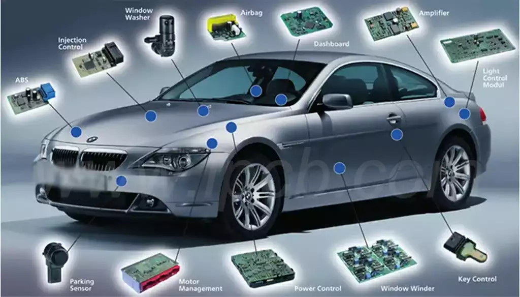
Rogers 5880 is also widely adopted in automotive radar and ADAS systems. With the advancement of autonomous driving technology, 77 GHz millimeter-wave radar has become a key component of vehicle perception systems, and Rogers 5880 is an ideal material for these radar antenna panels. Its extremely low dielectric loss improves antenna signal reception sensitivity, while its thermal stability ensures consistent electrical performance even in underhood or rooftop environments. Compared to ceramic antenna boards, Rogers 5880 offers advantages in cost, processing flexibility, and assembly process, making it the preferred high-frequency PCB material for automotive electronics manufacturers.
Rogers 5880 PCBs also play a key role in the medical device sector. Its excellent signal stability and high-frequency response make it suitable for MRI signal detection modules, heart rate monitors, and high-precision imaging systems. Given the stringent electromagnetic compatibility requirements of medical electronic equipment, Rogers 5880’s low loss characteristics not only reduce signal interference but also improve data acquisition accuracy, thereby enhancing the diagnostic performance and safety of the equipment.
Overall, the outstanding advantages of Rogers 5880 PCBs are reflected in the following aspects:
First, low dielectric loss ensures high signal transmission efficiency, making it particularly suitable for high-frequency and high-speed signal environments;
Second, its stable dielectric constant ensures precise impedance control, thereby improving system design reliability;
Third, its excellent thermomechanical properties enable it to maintain electrical consistency in harsh environments;
Fourth, its high processability enables complex multilayer structures and high-density interconnect designs.
These advantages make Rogers 5880 PCB the preferred material for many cutting-edge electronic systems. From 5G base stations to satellite communications, from automotive millimeter-wave radar to high-speed server motherboards, it ubiquitously supports the stable operation of high-performance electronic devices and leads the continuous evolution of high-frequency material technology.
Comparative Analysis of Rogers 5880 PCB with Other High-Frequency Materials
In the field of high-frequency and high-speed circuit design, the choice of materials directly determines signal integrity, system efficiency, and the reliability of the final product. Rogers 5880 PCB is favored not only for its excellent electrical performance but also for its comprehensive balanced performance among various high-frequency materials. To understand its true competitive advantage, we can systematically analyze its differences and applicability compared to other common high-frequency materials (such as Rogers 4350B, Rogers 4003C, Taconic TLY series, and the commonly used FR-4) from the dimensions of dielectric properties, thermal stability, processing characteristics, and cost structure.
First, from a dielectric performance perspective, Rogers 5880 has a dielectric constant of approximately 2.2, one of the lowest in the entire Rogers series. In comparison, the Rogers 4350B has a dielectric constant of 3.48, the Rogers 4003C has 3.38, and the Taconic TLY series ranges from approximately 2.17 to 2.55. A low dielectric constant means faster signal propagation and less delay in the medium, making it particularly suitable for high-frequency RF and millimeter-wave applications. More importantly, the Rogers 5880’s dielectric constant remains almost unchanged over a wide temperature range (-55°C to +150°C), while other materials exhibit significantly different dielectric constants over temperature variations.
Slight fluctuations are often observed during changes. This highly stable dielectric property makes the Rogers 5880 perform better in systems with extremely high phase consistency requirements, such as phased array radar and satellite communication antennas.
Secondly, in terms of dissipation factor, the Rogers 5880 has a loss of only about 0.0009 at 10 GHz, far lower than the Rogers 4350B’s 0.0037 and the FR-4’s 0.02. Low loss means minimal energy loss during signal transmission, ensuring a higher signal-to-noise ratio and lower insertion loss. This characteristic is particularly important for millimeter-wave communication links, high-speed interconnects, and high-precision radar systems. While some models in the Taconic TLY series can achieve similar loss levels, the Rogers 5880 exhibits significantly better batch consistency and long-term stability, which is crucial for mass production applications.
In terms of thermal performance and mechanical stability, the Rogers 5880 demonstrates an excellent balance. Its coefficient of thermal expansion (CTE) is approximately 16 ppm/℃, very close to that of copper (17 ppm/℃), resulting in extremely low interlayer stress during multilayer lamination and thermal cycling. This is significantly superior to Rogers 4003C (CTE approximately 46 ppm/℃) and ordinary FR-4 (CTE approximately 70 ppm/℃). This characteristic not only improves weld reliability but also prevents warping and cracking under high-temperature operating conditions. For aerospace systems and radar modules requiring long-term stable operation, the advantage of thermomechanical matching is a key factor affecting lifespan and reliability.
However, Rogers 5880 does not have an absolute advantage in all aspects. Due to the strong chemical inertness of its PTFE matrix, it is relatively difficult to process. Compared to high-frequency materials with ceramic fillers such as Rogers 4350B, 5880 is more prone to edge burrs or insufficient adhesion during drilling, etching, and lamination. This means manufacturers must possess specialized high-frequency board processing capabilities, such as plasma cleaning, activated surface treatment, low-speed drilling, and high-precision lamination control. Improper use can easily lead to poor copper adhesion in the holes or linewidth deviations. In comparison, Rogers 4350B and 4003C are easier to process and more suitable for mass production, thus being more commonly used in the mid-to-high frequency range (1GHz~10GHz), while Rogers 5880 is more often used in high-end projects requiring extreme performance.
From a cost structure perspective, the price of Rogers 5880 is typically 40% to 80% higher than Rogers 4350B and 4003C. This difference mainly stems from the increased cost and manufacturing difficulty of the PTFE composite process. However, with the widespread adoption of high-frequency communication and millimeter-wave radar, the performance advantages of 5880 often offset its price difference. For example, in 5G antenna array design, using Rogers 5880 can significantly improve signal gain and bandwidth stability, thereby reducing the number of antennas or simplifying amplification modules, resulting in a decrease in overall system cost. Therefore, from a system-level cost optimization perspective, Rogers 5880 is a material with an extremely high return on investment.
From an application suitability perspective, Rogers 5880 is positioned closer to a “high-frequency limit material.” Its advantage lies in maintaining excellent signal quality at extremely high frequencies (>40GHz), making it ideal for radar, satellite communications, millimeter-wave links, avionics, and precision antenna systems. Rogers 4350B and 4003C, on the other hand, are more suitable for high-frequency applications below 10GHz, such as wireless base stations, filters, and power dividers. The Taconic series, due to its lightweight characteristics and low water absorption, also holds a place in the aerospace and medical imaging fields, but in large-scale industrial applications, its consistency and global supply chain capabilities still lag behind the Rogers brand.
Furthermore, Rogers 5880 exhibits excellent electromagnetic compatibility (EMC) advantages. Low dielectric loss not only reduces signal reflection and crosstalk but also suppresses high-frequency radiated noise. Many system design engineers specializing in 5G RF front-ends and satellite communication modules have noted a significant decrease in electromagnetic interference (EMI) and a 5% to 8% improvement in power efficiency after using Rogers 5880. This data indicates that 5880 surpasses the performance limits of traditional materials in terms of electrical cleanliness in high-frequency systems.
In summary, the difference between Rogers 5880 and other high-frequency materials can be attributed to a trade-off between performance and manufacturability. It represents the pinnacle of high-frequency PCB material performance, virtually unmatched in signal integrity, stability, and thermal management; however, it also demands mature processing capabilities and stringent quality control systems from manufacturers. In other words, Rogers 5880 is a material designed for “extreme performance,” suitable for mission-critical applications where signal loss and phase deviation are intolerable.
The Key Role of Rogers 5880 PCBs in RF and Microwave Applications
With the rapid development of wireless communication, radar systems, satellite navigation, aerospace, and autonomous driving, the performance requirements of RF and microwave circuits on PCBs have become unprecedentedly demanding. Traditional FR-4 materials, due to their high dielectric loss, unstable dielectric constant, and severe signal attenuation, are no longer suitable for high-frequency applications. Rogers 5880 PCBs, with their superior dielectric properties, extremely low signal loss, and excellent dimensional stability, have become one of the preferred materials for RF and microwave circuit design.
One of the most significant characteristics of Rogers 5880 materials is their extremely low dielectric constant (Dk≈2.20) and dielectric loss (Df≈0.0009), which results in virtually no phase delay and energy attenuation during signal transmission. For circuits operating at GHz or even higher frequencies, this performance translates to higher signal integrity and lower crosstalk risk. For example, in systems such as 5G base station antennas, millimeter-wave radar, and satellite communication modules, the stability of the signal path directly determines the system’s sensitivity and reliability. Rogers 5880 PCBs maintain minimal insertion loss and excellent impedance consistency in these high-frequency links, ensuring accurate and efficient data transmission.
Impedance control is a crucial aspect of RF circuit design. Rogers 5880’s uniform dielectric constant and low moisture absorption enable it to maintain extremely high impedance stability in various operating environments. This is particularly critical for aerospace, military radar, and satellite communication equipment, as these systems typically operate under extreme temperature, humidity, and vibration conditions, where ordinary PCB materials are prone to performance drift or interlayer delamination. The mechanical and chemical stability of Rogers 5880 ensures consistent signal transmission paths over long-term operation, reducing system distortion.
Furthermore, Rogers 5880 exhibits excellent electromagnetic compatibility (EMC) performance. Its low dielectric loss and superior signal confinement properties effectively reduce radiated interference and signal leakage, thereby enhancing the system’s immunity to interference. For military communication equipment, navigation systems, and high-precision testing instruments, this low-noise characteristic not only improves system performance but also reduces the risk of interference from the external environment, meeting stringent EMC standards.
In microwave circuit design, Rogers 5880 PCBs have a wide range of applications, including power amplifiers, mixers, filters, antenna arrays, and phased array radar modules. Taking antennas as an example, the antenna substrate’s influence on signal reflection and energy distribution is crucial. Using Rogers 5880 as the antenna substrate material not only achieves higher radiation efficiency but also allows the antenna to maintain stable gain and directivity across a wider frequency band. Its low dielectric constant effectively reduces signal propagation delay, resulting in more precise phase control of the antenna array and significantly improving the resolution and target recognition capabilities of the radar system.
Furthermore, the advantages of Rogers 5880 are even more pronounced in millimeter-wave and terahertz band applications. Because it maintains stable dielectric properties at high frequencies, it is widely used in automotive millimeter-wave radar, drone obstacle avoidance systems, and high-speed wireless communication modules. Especially with the development of 5G and future 6G communication technologies, the continuously increasing signal frequencies place higher demands on the dielectric properties of PCB materials. The emergence of Rogers 5880 perfectly aligns with this trend of high frequency and low loss, providing a solid material foundation for the evolution of wireless technology.
More importantly, Rogers 5880 supports multilayer structures and hybrid stack-up processes, allowing it to be used in conjunction with other high-frequency materials (such as Rogers 4003C or the PTFE series) to achieve functional optimization and cost control. This flexible material combination capability enables designers to balance performance and price in different functional modules, creating RF system solutions that combine high performance and economy.
In short, Rogers 5880 PCB is not merely a high-performance material, but a key technological cornerstone of the high-frequency era. It frees RF and microwave circuit design from material bottlenecks, enabling high-frequency signals to traverse every corner of the circuit world with higher efficiency and lower loss, opening new doors for the development of high-speed communication, precision radar, navigation and positioning, and even quantum technology.
Conclusion
the emergence of Rogers 5880 PCB provides solid support for the development of high-frequency and high-speed electronic technologies. Whether in 5G communications, aerospace, radar systems, or satellite navigation, this high-performance material stands out for its low dielectric constant, extremely low loss factor, and excellent stability. It not only solves the delay and distortion problems that traditional PCBs easily encounter in signal transmission, but also wins the favor of engineers and manufacturers with its high reliability and excellent environmental adaptability. It can be said that Rogers 5880 is not just a circuit material, but a technology accelerator, propelling wireless communication and microwave engineering into a new era of faster, more stable, and more efficient performance. As the requirements for high-frequency signal integrity continue to increase in the future, Rogers 5880 PCBs will continue to play a crucial role, leading the electronics manufacturing industry to even higher performance limits.
