Introduction and Background
Amid the rapid development of today’s high-speed digital and radio frequency electronics industries, circuit board materials and structural design are becoming crucial for corporate competitiveness. While traditional FR4 material is adequate for many common applications, its performance bottleneck is becoming increasingly apparent when it comes to 5G communications, high-speed data transmission, satellite navigation, automotive radar, and aerospace systems. To meet these stringent requirements for high frequency, high reliability, and complex interconnects, specialized Rogers HDI PCBs have emerged.
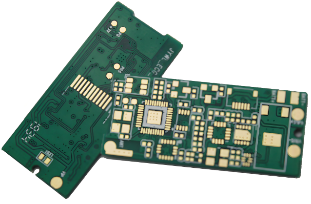
“Rogers material” refers to a high-performance, high-frequency copper-clad laminate developed by Rogers Corporation. It surpasses conventional epoxy-based laminates in terms of dielectric constant (Dk), dissipation factor (Df), and coefficient of thermal expansion (CTE). Compared to traditional FR4, Rogers material maintains stable electrical performance at GHz frequencies, making it widely used in high-frequency and high-speed circuits. When these high-performance materials are combined with high-density interconnect (HDI) technology, the result is the Rogers Special HDI PCB. It not only delivers exceptional electrical performance but also offers significant advantages in design flexibility, lightweighting, and miniaturization.
The introduction of HDI technology has significantly advanced PCB routing density and functional integration. Through processes such as blind and buried vias and laser microvias, engineers can achieve greater signal interconnection within limited space, significantly increasing design freedom and system integration. This advanced process, combined with Rogers’ specialized materials, addresses integrity issues in high-speed signal transmission while ensuring stability and reliability in extreme temperature, humidity, and vibration environments.
The Rogers Special HDI PCB has become an indispensable component in high-end electronics manufacturing. It’s more than just a circuit board; it’s a core platform supporting future technological advancements. With the continued development of 5G, satellite communications, millimeter-wave radar, and artificial intelligence hardware, demand for this type of high-performance PCB will continue to rise.
Material and Structural Characteristics
In all circuit board designs, material selection often determines the upper limit of the final product’s performance, while structural design influences process implementation and reliability. For special Rogers HDI PCBs, these two aspects complement each other, supporting their widespread use in high-end applications.
Core Characteristics of Rogers Materials
Rogers’ high-frequency copper-clad laminates differ significantly from traditional FR4. First, Rogers materials offer stable and precise dielectric constant (Dk), which is particularly critical for high-speed signal transmission, as Dk fluctuations directly lead to signal delay and distortion. Second, Rogers laminates exhibit extremely low dissipation factor (Df), which minimizes signal energy loss at GHz and even millimeter-wave frequencies, maintaining excellent transmission efficiency.
In addition to electrical performance, Rogers materials also exhibit excellent thermal and dimensional stability. Traditional FR4 is susceptible to thermal expansion and warping in high-temperature environments, but Rogers’ material’s low CTE (coefficient of thermal expansion) ensures a stable structure even under repeated hot and cold cycles, preventing damage to device solder joints or wiring. This stability is particularly critical in applications requiring long-term, reliable operation, such as automotive radar and satellite communications.
Unique Advantages of HDI Structure
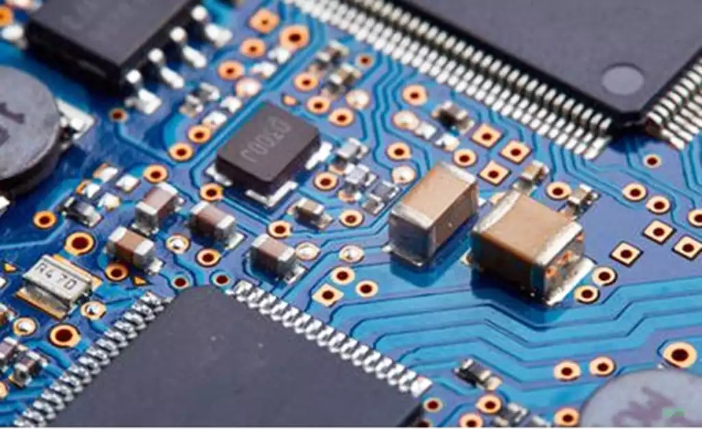
The emergence of HDI (High Density Interconnect) technology has revolutionized PCB design. Traditional multilayer PCBs are limited by through-hole processes, making it difficult to achieve high routing density. HDI, by utilizing blind, buried, and microvias, significantly increases routing freedom and interconnect efficiency. This structural advantage is even more evident in special Rogers HDI PCBs.
First, HDI structures shorten signal paths. Since high-speed signal transmission is extremely sensitive to path length, HDI’s microvia design allows signals to travel more directly between layers, reducing signal latency and reflections. Second, HDI allows for the integration of more functional modules within a limited area, which is crucial for miniaturized and lightweight device design. For example, in millimeter-wave antenna modules, engineers can implement complex routing and RF matching within a limited area without sacrificing performance.
The Combination of Materials and Structures
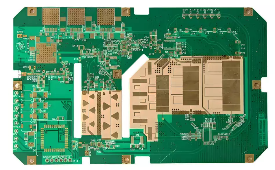
When Rogers materials are combined with HDI structures, the results far exceed those of either technology alone. Rogers materials guarantee high-frequency electrical performance, while HDI structures ensure routing density and interconnect efficiency. This combination allows designers to confidently route signals at GHz and higher frequencies while achieving high functional integration within a limited space.
For example, in the active antenna arrays of 5G base stations, Rogers materials provide extremely low signal loss and a stable dielectric constant, while HDI structures enable the compact integration of hundreds of RF channels, enabling high-speed, high-capacity data transmission. In satellite communication terminals, for example, the combined structure can withstand the extreme temperature fluctuations of space while maintaining signal integrity and low loss.
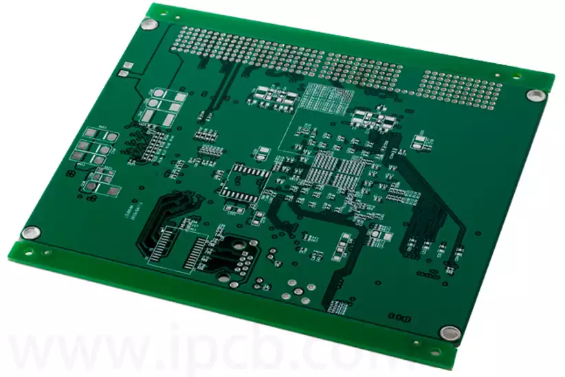
Differences from Traditional Structures
Compared to FR4 multilayer boards, the differences of special Rogers HDI PCBs lie not only in material performance but also in the possibilities for system-level design. FR4 substrates often suffer from unacceptable signal attenuation at high frequencies, while HDI technology, when applied to FR4, cannot fully realize its expected performance. Only the combination of a high-performance substrate like Rogers and HDI technology can truly resolve the bottleneck in high-frequency signal transmission.
This difference makes the Special Rogers HDI PCB board not just a simple replacement for traditional circuit boards, but a solution specifically designed for future high-performance electronic systems. It not only meets the current needs of 5G, radar, and aerospace, but also lays a solid foundation for upcoming cutting-edge fields such as 6G, artificial intelligence hardware, and quantum communications.
Manufacturing Process and Technical Challenges
Manufacturing a Special Rogers HDI PCB board is not a simple stacking of materials; it involves a systematic engineering process involving precision engineering, strict control, and complex processes. The inherent properties of the Rogers material and the high requirements of the HDI process make the production of this type of circuit board more challenging than that of traditional FR4.
Material Processing Difficulties
Rogers substrate differs significantly from FR4 in chemical and physical properties. Its low water absorption and strong chemical stability mean that traditional FR4 process parameters are often no longer applicable during drilling, etching, and lamination.
Drilling Challenges: Due to the flexibility and special composition of Rogers material, mechanical drilling is prone to burrs and uneven hole walls. Laser drilling, on the other hand, requires precise energy control to avoid overburning or hole diameter deviation.
Etching Difficulty: Rogers board exhibits different tolerance to etching solutions than FR4. Improper control can easily lead to rough trace edges, compromising high-frequency signal integrity.
Lamination Process: The thermal expansion coefficient of Rogers substrate differs from that of conventional bonding sheets, easily generating internal stress during lamination. Failure to properly control this can cause board warping or delamination.
HDI Process Complexity
HDI circuit boards rely on processes such as blind vias, buried vias, and microvias, all of which place extremely high demands on manufacturing precision.
Laser Microvia: Microvia diameters are typically less than 150μm, requiring smooth hole walls and no carbonized residue. This places stringent requirements on both laser energy control and post-process cleaning.
Multiple Laminations: HDI designs often require multiple laminations, each of which can introduce interlayer misalignment or stress concentration. Rogers materials are temperature-sensitive, requiring more precise thermal profile control.
Conduction Reliability: The uniformity of microvia copper plating directly determines the stability of signal transmission. High-reliability via metallization on Rogers substrates requires improved electroless and electroplating processes.
Process Integration Challenges
Rogers materials offer advantages in electrical performance, but they are often more expensive than FR4. Therefore, production must not only ensure performance but also improve yield to reduce costs.
Mixed Lamination of Different Materials: In practical applications, some designs mix Rogers and FR4 to balance performance and cost. However, due to differences in thermal expansion, moisture absorption, and mechanical strength between the two materials, mixed lamination is prone to warping and delamination, requiring manufacturers to have extensive process experience.
Signal Integrity Testing: At gigahertz frequencies, even the slightest process deviation can cause signal distortion or reflection. Therefore, process control isn’t limited to physical processing; it also requires verification throughout the entire design and manufacturing process, combined with simulation and testing.
Common Industry Pain Points
Despite strong demand for special Rogers HDI PCBs in high-performance applications, the industry still faces some common challenges.
High Production Costs: The high price of Rogers substrates, coupled with the multiple lamination processes and delicate processes involved in HDI, make the overall manufacturing cost far higher than that of ordinary PCBs.
Difficulty in Improving Yield: Due to the complex process steps involved, problems during drilling, lamination, or plating can render the entire board scrapped.
High Equipment Investment: Producing this type of circuit board requires expensive equipment such as laser drilling machines, high-precision exposure equipment, and automated plating lines, which are often unaffordable for small and medium-sized manufacturers.
These challenges mean that not all PCB manufacturers have the capability to produce special Rogers HDI PCBs. The ability to achieve stable mass production has become a key criterion for measuring a company’s technological strength and market competitiveness.
Process Challenges and Solutions for Special Rogers HDI PCBs
In the electronics manufacturing industry, HDI PCBs are often considered a concentrated embodiment of process and technology. However, when combined with Rogers high-frequency materials, the entire manufacturing process presents even greater challenges. Special Rogers HDI PCBs not only place high demands on material properties, but also impose stringent standards in design, production, and testing. The following will discuss solutions based on several major process challenges and common industry practices.
Microvia Drilling Precision Control
Microvias are a core feature of HDI PCBs. Due to differences in the dielectric and thermal properties of Rogers materials compared to traditional FR-4, microvia drilling is prone to deviation, burrs, and even hole wall damage. To avoid these issues, manufacturers typically utilize laser drilling technology, optimizing laser energy density, pulse frequency, and processing speed to achieve consistent hole diameters. Furthermore, the post-drilling desmearing process must be tailored to the chemical properties of the Rogers material to ensure reliable hole wall adhesion during subsequent copper plating.
Thermal Stress Challenges in the Lamination Process
Rogers high-frequency material has a different coefficient of thermal expansion (CTE) than traditional FR-4. When the two are mixed and laminated, internal stress can easily occur, leading to warping and even delamination. Solutions to this problem include selecting Rogers material grades with lower CTEs, optimizing the lamination temperature profile, and using specialized adhesive sheets to alleviate interfacial stress. Some manufacturers also employ a staged pressurization method, gradually increasing the temperature within different temperature ranges to ensure more uniform resin flow and curing.
Surface Finish Compatibility
Since HDI circuit boards are often used in high-speed signal or high-frequency applications, the surface finish must balance electrical conductivity and signal integrity. Common finishes include ENIG (electroless nickel gold), immersion silver, and immersion tin. However, selecting the wrong surface finish for Rogers material can increase signal loss or reduce soldering reliability. Therefore, manufacturers need to consider customer application requirements, assess cost and performance, and recommend an appropriate surface finish. For example, in millimeter-wave communications, immersion silver is often considered to offer both high conductivity and low loss.
The Complexity of Impedance Control
In high-speed and high-frequency circuits, impedance control directly determines signal transmission quality. Impedance design for special Rogers HDI PCB boards depends not only on the dielectric constant of the material but also closely on trace width, copper thickness, and layer spacing. While the dielectric constant of Rogers material is more stable than that of FR-4, slight process variations during production can still cause impedance variations. Therefore, manufacturers often use impedance test boards during production and conduct sampling inspections within each batch to ensure consistency. Some high-end projects even require 100% inspection to mitigate any potential risks.
Balancing Cost and Yield
Rogers material itself is expensive, and coupled with the complex multiple lamination and drilling processes of HDI, manufacturing costs are significantly higher than those of conventional PCBs. Low yields during manufacturing can directly impact customer project schedules and overall budgets. The key to addressing this issue lies in early design-for-manufacturing (DFM) reviews by engineers. By optimizing the stackup design, reducing unnecessary blind and buried vias, and properly arranging copper thickness and traces, manufacturing feasibility and yield can be improved.
As can be seen, Special Rogers HDI PCB boards require not only careful material selection but also extensive experience and technical expertise in the manufacturing process. For customers, choosing a supplier with proven manufacturing experience directly determines project success and delivery efficiency.
Typical Applications and Case Studies
Special Rogers HDI PCBs, due to their excellent high-frequency performance, high-density interconnect capabilities, and stable and reliable structure, have been widely used in various high-end electronics fields. Understanding their application scenarios not only helps technical personnel grasp design principles but also allows procurement and new industry personnel to appreciate their practical value.
5G Communication Equipment
With the rapid deployment of 5G networks, high-frequency signal processing and high-speed data transmission have become core requirements for device design. The low dielectric loss characteristics of Special Rogers HDI PCBs ensure stable and efficient signal transmission in the GHz and even millimeter-wave frequency bands. The microvia and buried via design of the HDI structure enable compact placement of multi-layer antenna arrays and RF modules, significantly shortening signal paths and reducing latency. In a real-world case, a domestic 5G base station antenna module employed Rogers HDI multilayer boards. While the original FR4 board experienced a signal attenuation rate exceeding 1.2dB in the 3.5GHz frequency band, the Rogers HDI board exhibited a signal attenuation rate of only 0.3dB, effectively improving signal quality and module stability.
Satellite Communications and Radar Systems
Satellite communications and radar systems require thermal stability of circuit boards.High performance and signal integrity requirements are extremely high. Special Rogers materials maintain stable dielectric properties in temperatures ranging from -55°C to +125°C, while HDI’s high-density wiring ensures compact integration of complex antennas and RF front-end modules.
For example, a satellite communication terminal manufacturer, using special Rogers HDI PCBs, reduced the antenna module area by approximately 30% while improving the signal-to-noise ratio by 15%, effectively enhancing the overall performance of the terminal.
Automotive Electronics and Radar Sensors
With the advancement of intelligent driving, automotive radar and ADAS (Advanced Driver Assistance Systems) are placing higher demands on PCB performance. High-speed radar signal transmission requires low loss and precise impedance matching, and special Rogers materials ensure high-speed signal integrity. HDI technology allows for the placement of complex sensor circuits and control modules in limited space.
A well-known automobile manufacturer used special Rogers HDI PCBs in its radar modules, which improved detection accuracy by approximately 20% in high-speed driving environments and reduced module weight by 15%, supporting vehicle lightweighting and performance optimization.
Aerospace and Military Applications
Aerospace and military electronic systems require not only high-frequency performance but also reliability in extreme environments. Special Rogers HDI PCB boards maintain excellent signal transmission and mechanical stability under conditions of high altitude, low temperature, high humidity, and strong vibration, making them suitable for satellite control, radar systems, and navigation equipment.
For example, a US space program employed Rogers HDI boards in microwave communication boards. These boards have undergone multiple high-temperature cycling and vibration tests and have maintained zero-failure operation, ensuring reliable signal transmission for spacecraft.
High-End Industrial Electronics and Medical Equipment
In high-end industrial control and medical imaging equipment, PCB signal integrity and compact layout are critical to system performance. Special Rogers HDI PCB boards’ high-precision microvias, low loss, and high-frequency stability make them suitable for ultrasound imaging systems, precision instruments, and industrial automation control modules.
For example, a medical imaging equipment manufacturer employed Rogers HDI PCBs in high-frequency acquisition modules, achieving higher image acquisition accuracy and data processing speed while reducing device size and providing more convenient space for clinical operations.
Summary
The above examples demonstrate that Special Rogers HDI PCBs are more than just technological advancements; they truly provide core support for performance assurance and design flexibility in high-end applications. From 5G communications to aerospace, automotive radar to medical imaging, their application value lies not only in the performance of individual boards, but also in the reliability and integration capabilities of system-level solutions.
Manufacturing Process Optimization and Quality Control
The key to producing Special Rogers HDI PCBs lies not only in the materials and design itself, but also in rigorous manufacturing processes and comprehensive quality control. Due to the combination of the characteristics of Rogers’ high-frequency materials and the complex structure of HDI, the production process for this type of PCB involves multiple critical steps, each of which directly impacts the final performance. Optimizing processes and controlling quality are key to ensuring stable performance and reducing costs.
Design for Manufacturing (DFM) Assessment in the Design Phase
Before manufacturing, the engineering team needs to perform a DFM (Design for Manufacturing) analysis on the PCB design. This phase focuses on the following:
Aperture and Blind Via Layout: Via location, aperture size, and interlayer routing density all require feasibility verification to ensure smooth execution of subsequent drilling and plating processes.
Impedance Matching and Signal Paths: Through simulation analysis of signal transmission paths, trace widths and layer spacing are adjusted to ensure high-speed signal integrity.
Material Selection and Lamination Sequence: The Rogers material type, copper thickness, and stacking sequence used for each layer are determined to minimize thermal expansion and warping issues.
DFM optimization can prevent most manufacturing risks during the design phase, thereby improving first-article success rates and overall yield.
Precision Drilling and Microvia Processing
Microvia processing is one of the most critical processes in HDI circuit boards. Due to the unique characteristics of Rogers materials, manufacturers typically use laser drilling technology, combined with high-precision positioning and stable energy control, to achieve precise and consistent hole diameters. Post-drilling desmearing, hole cleaning, and drying must also be performed strictly in accordance with material properties to ensure clean and contaminant-free hole walls, providing a reliable foundation for subsequent plating.
Multiple Laminations and Thermal Stress Control
HDI boards typically require multiple laminations, each of which can introduce stress. While Rogers materials offer a low and stable CTE, mixed lamination of multiple materials still carries the risk of warpage. Solutions include:
Precisely controlling the heating rate and temperature profile, and applying pressurization in stages to reduce thermal stress accumulation.
Using specialized bonding sheets and low-expansion materials to alleviate interlaminar stress.
Performing warpage detection and correction after lamination to ensure board flatness.
Precision Electroplating and Surface Treatment
The quality of copper plating in HDI microvias directly impacts signal transmission reliability. Manufacturers typically use a combination of electroless plating and electroplating to ensure uniform copper thickness and strong adhesion on the via walls. Surface treatments (such as ENIG, immersion silver, or immersion tin) must be compatible with Rogers materials to ensure both solderability and high-frequency signal performance.
Comprehensive Quality Control and Testing
To ensure that each batch of boards meets high-performance requirements, quality control includes:
Optical inspection and X-ray inspection: Checking the accuracy of blind and buried vias and multi-layer stacking.
Impedance testing: Ensures that the impedance of each high-speed signal trace meets design requirements.
Functional and aging testing: Temperature, humidity, and vibration tests are conducted in simulated operating environments to ensure long-term reliable board operation.
Through rigorous process optimization and comprehensive quality control, manufacturers are able to stably produce Special Rogers HDI PCBs under challenging conditions, improving yield and reducing rework rates, thereby providing a stable and reliable core foundation for high-end electronic systems.
Future Development Trends and Technology Outlook
With the continuous development of high-frequency and high-speed electronic systems, the demand for Special Rogers HDI PCBs will only continue to grow, and manufacturing technology, material selection, and design concepts are also evolving. Understanding future development trends will help technicians, procurement, and new industry professionals grasp market trends and plan ahead in design and production.
High-Frequency Signals and Higher-Layer-Count HDI Boards
The development of 5G, millimeter-wave communications, and satellite communications has placed higher demands on PCB frequencies and data transmission rates. Future HDI boards may feature higher layer counts, more compact microvias, and more complex stacking structures to meet signal integrity and compact design requirements. This means manufacturers need to further improve laser drilling accuracy, multi-pass lamination stability, and hole-wall plating uniformity.
Application of New High-Frequency Materials
While Rogers materials are widely used, a new generation of high-frequency materials is under development, offering lower dielectric loss, more stable thermal expansion coefficients, and superior mechanical properties. The emergence of these materials will promote the use of special Rogers HDI PCBs in more extreme environments, potentially leading to higher yields and lower costs.
Smart Manufacturing and Automation
The future manufacturing trend is full-process intelligence:
Inline inspection: Using machine vision and AI algorithms, real-time defect detection is achieved, reducing human error.
Automated drilling and copper plating: Combining advanced robotics and precision control, this enables efficient processing of microvias, blind vias, and buried vias.
Data-driven process optimization: Using big data analysis of production data, we optimize lamination, surface treatment, and testing processes, improving yield and production stability.
Sustainable and Green Manufacturing
With growing global environmental awareness, PCB manufacturing is also seeking greener production methods. These include reducing the use of hazardous chemicals, minimizing wastewater and exhaust emissions, and improving material utilization. Future Rogers HDI PCB production will gradually move toward low-carbon and environmentally friendly approaches while maintaining performance.
Deep Integration with Emerging Electronic Systems
Special Rogers HDI PCBs will play an even more core role in future smart cars, aerospace, medical imaging, and industrial control systems. As electronic systems grow in complexity, the demands on PCB signal integrity, power consumption control, thermal performance, and reliability will also increase. Manufacturers and designers must continuously innovate in materials, processes, and design strategies to meet overall system performance requirements.
Summary
Overall, the development trend of Special Rogers HDI PCBs is characterized by higher layer counts, higher frequencies, intelligent manufacturing, and green manufacturing. With material innovation, process optimization, and improved automation, their application in high-end electronic systems will become even more widespread, becoming a key foundation for driving upgrades and technological innovation in the electronics industry.