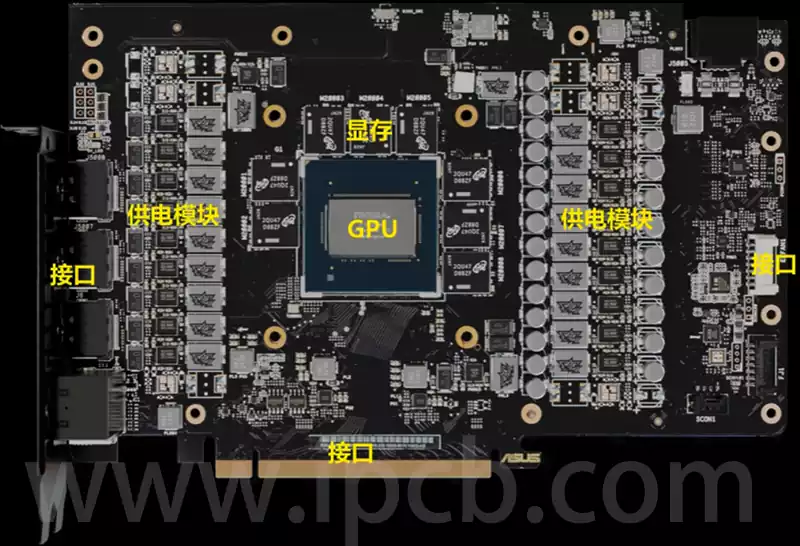
On a graphics card pcb, the power supply section is just as critical as the graphics processing unit (GPU). If the GPU is the ‘brain’ of the graphics card, then the power supply section is its ‘heart.’ Without a robust ‘heart’ providing foundational support, even the most powerful ‘brain’ cannot function properly. Additionally, the design quality of the power supply system directly impacts the overall performance of the graphics card. For example, high-end GPUs require a powerful power supply system to operate, which is one of the primary differences between top-tier graphics cards and ordinary ones.
Types of graphics card pcb power supply systems
The core elements required for GPU operation are precise voltage and current. The primary function of the graphics card pcb power supply system is to ensure that the GPU receives stable, clean, and appropriate voltage and current through operations such as voltage regulation, stabilisation, and filtering. The power supply systems applied to graphics cards are primarily divided into three types, all of which operate in a buck mode, meaning the output voltage is always lower than the input voltage.
Three-terminal voltage regulator circuit: This is a historically established and relatively simple graphics card pcb power supply system. It only requires an integrated voltage regulator to operate, but its current supply capacity is limited and it is not suitable for high-load devices. Therefore, for components like GPUs that have high requirements for current and voltage, the three-terminal voltage regulator circuit cannot directly drive them and is currently mainly used for powering DAC circuits or interfaces.
Field-effect transistor (FET) voltage regulator circuit: This power supply system emerged earlier and primarily consists of signal driver chips and MOSFETs. It offers advantages such as fast response speed, low output ripple, and low operating noise, while also being cost-effective. However, it has low conversion efficiency and generates significant heat, which is unfavourable for power consumption and temperature control. As a result, it is primarily used for powering graphics memory PCBs or low-end graphics card products. With technological advancements, this power supply system has gradually faded from the market.
Switching Circuit System: Currently, the switching circuit system is the most widely used power supply method in graphics card PCBs. Considering that the first two power supply systems cannot meet the high load requirements of GPUs, graphics card manufacturers have universally adopted more advanced switching circuits. The switching circuit maintains a stable output voltage by controlling the conduction and cutoff time and ratio of the switching transistor. It primarily consists of capacitors, inductors, MOSFET field-effect transistors, and PWM pulse width modulation ICs. This circuit system has low heat generation, high conversion efficiency, a wide voltage regulation range, and excellent voltage regulation performance, making it the preferred power supply solution for graphics cards.
The working principle of the switching circuit and the advantages of multi-phase power supply
The switching circuit begins with a 12V voltage input from the PCI-E interface and auxiliary power supply interface. To ensure current stability, the input current first passes through a large capacitor for filtering. The filtered current then enters the circuit controlled by the PWM chip. Since the 12V voltage cannot be directly input to the GPU core (the GPU’s operating voltage is typically around 1.2V), a voltage-reduction process is necessary. The MOSFET transistors controlled by the PWM chip generate a specific frequency waveform voltage through continuous operations of ‘opening the upper bridge and closing the lower bridge, then closing the upper bridge and opening the lower bridge.’ The frequency of the waveform voltage affects its voltage value. Through precise control by the PWM chip, the desired output voltage value can be generated.
Although the appropriate voltage is obtained, the current at this point is an intermittent waveform. To achieve a smooth current, the energy storage function of the inductor is utilised. By charging and discharging a large-capacity inductor, a voltage close to a straight line can be generated. Finally, the current flows through the output filter capacitor composed of small-capacity capacitors, thereby outputting the ideal GPU voltage. In this process, the PWM chip precisely regulates the voltage supplied to each phase to ensure it reaches the set ideal voltage value. The capacitor stabilises the supply voltage and filters out noise in the current, making the current purer. The inductor coil stabilises the current through energy storage and release.
From the perspective of the working principle of the graphics card PCB circuit, the simpler the switch circuit design, the better. This is because, from a probabilistic analysis, each component has a certain ‘failure rate.’ The more components used, the higher the total failure rate of the system, thereby increasing the probability of issues occurring. However, high-end graphics cards have high power consumption. If a single-phase power supply circuit is used, components capable of handling high power and current must be employed, which results in significant heat generation and also incurs very high costs on the graphics card PCB. Therefore, almost all graphics card PCBs adopt a multi-phase power supply design.
Multi-phase power supply offers the following advantages:
Provides greater current: Multi-phase power supply can deliver a larger current output to the graphics card, meeting the high power consumption requirements of the GPU.
Reduces power supply circuit temperature: Current is distributed across multiple paths, reducing heat generation per component and effectively lowering the overall temperature of the power supply circuit.
Precise current balancing: Multi-phase power supply circuits can precisely balance the output current across each phase, maintaining thermal equilibrium among power components.
Improved voltage signal stability: Compared to single-phase power supply, multi-phase power supply provides a more stable core voltage signal.
The drawbacks of multi-phase power supply include higher costs and stricter requirements for wiring design and heat dissipation. Therefore, the more high-end the product, the more power phases it employs.
The graphics card pcb power supply system is the foundation for its stable operation and performance, with importance on par with the GPU core. If the GPU is likened to the ‘brain,’ the power supply section is the ‘heart’ providing robust support. A high-quality power supply system ensures the GPU receives stable, clean voltage and current, directly impacting the graphics card’s performance.
The graphics card power supply system plays a crucial role as its core driving force on the graphics card PCB. Its complexity and sophisticated design are equally important as the GPU itself. Technological advances have always focused on providing more stable and efficient power output to meet the ever-increasing performance demands of GPUs.