What is impedance? The impedance of an alternating current in a circuit with resistance, capacitance, or inductance is called impedance, and is often denoted by the letter Z in ohms. It is a complex number, the real part is resistance, the imaginary part is reactance, where the capacitance of the alternating current in the circuit is called capacitive reactance, the inductance of the alternating current in the circuit is called inductive reactance, and the capacitance and the inductance in the circuit of the alternating current caused by the obstruction of the total is called reactance.
It is usually labeled with the symbol Z.
Impedance (Z) is the obstruction of alternating current by a circuit with resistance, inductance, and capacitance; it is a complex number with the real part called resistance (R) and the imaginary part called reactance (X).
Impedance, which is the sum of resistance and reactance, is expressed in mathematical form as:
Z = R + jX.
When X > 0, it is called inductive reactance
When X = 0, the impedance is pure resistance
When X < 0, it is called capacitive reactance
For an ideal purely inductive or capacitive element with zero resistance, the impedance strength is the magnitude of the reactance.
The total reactance of a general circuit is equal to:
X=XL-XC
Where XL is the inductive reactance of the circuit and XC is the capacitive reactance of the circuit.
In reality, most loads are inductive, such as transformers and motors. Defining inductive reactance as positive and capacitive reactance as negative avoids the appearance of negative numbers and facilitates calculations.
To summarize their relationship:
Impedance = Resistance + Reactance
Where Resistance is Resistance, not Resistor.
Reactance = Inductive + Capacitive
where inductive reactance is defined as positive and capacitive reactance as negative.
It is the grandfather who has two sons: Resistance and Reactance. Reactance has two grandchildren: inductive reactance and capacitive reactance.
Inductive Reactance
Inductive Reactance is the resistance of an inductor to an alternating current. The main characteristic of inductors is that they can store energy in a magnetic field, which is generated by the current flowing through the inductor.
Reactance is characterized as being proportional to frequency. That is, as the frequency of the alternating current rises, the inductive reactance increases and the more the inductor impedes the current. As the frequency falls, the inductance decreases and the impedance to the current is smaller.
The formula is: XL = 2πfL, where XL is the reactance, f is the frequency, and L is the inductance.
Capacitive Reactance:
In an AC circuit, the impedance of a capacitor to current is the capacitive reactance. The magnitude of capacitive reactance is expressed by the following formula:
XC= 1/(ωC) = 1/(2πfC)
XC is the capacitive reactance, the international unit is ohm (Ω);
ω is the angular frequency of alternating current, the international unit is radian/s (rad/s);
f is the frequency of alternating current, the international unit is Hertz (Hz);
C is the capacitance of the capacitor, the international unit is farad (F).
Obviously, the magnitude of capacitive reactance is not only related to its own factor (C), but also to the angular frequency (ω) or frequency (f) of the externally applied alternating current.
The larger the capacitance C of the capacitor, the smaller the capacitive reactance XC.
The higher the angular frequency ω or frequency f of the alternating current, the smaller the capacitive reactance XC, the smaller the obstruction of the alternating current, which is the capacitor has a high frequency resistance to low-frequency characteristics.
DC frequency we can think of as zero, so the capacitive reactance is infinite, the impedance of DC is also infinite, which is the capacitor has the characteristic of isolation flow AC.
Resistance is the resistance that the current encounters in a circuit, or the ability of an object to impede the current. The greater the resistance, the greater the resistance of the current, and therefore the current is smaller. Conversely, the smaller the resistance, the smaller the resistance of the current, and therefore the current is greater.
The symbol for resistance is “R”. The unit of resistance is the ohm, or ohm for short, and is expressed by the letter “Ω”.
Factors affecting the impedance of printed circuit boards
- Dielectric thickness
Dielectric thickness has a significant impact on the characteristic impedance of the printed circuit board, usually increase the thickness of the medium will increase the impedance, while reducing the thickness of the medium will reduce the impedance. This is because the characteristic impedance is proportional to the natural logarithm of the thickness of the medium, so the design needs to be reasonable to set the thickness of each layer to meet the impedance control requirements. - Copper thickness
Copper thickness is also an important factor affecting the impedance, reduce the copper thickness of the circuit conductor can increase the impedance, and vice versa, increase the copper thickness will reduce the impedance. In the design to ensure that the copper layer thickness uniformity, so as not to cause impedance fluctuations. - Alignment width and spacing
The width and spacing of the alignment is directly related to the impedance value, usually wider wires will reduce impedance, while narrower wires will increase impedance. Similarly, changes in the spacing of the alignment will also have an impact on the signal transmission, the smaller the spacing of the alignment may increase the signal coupling, but it may also make the impedance matching becomes complicated. - Dielectric Constant
The dielectric constant of a material has an inverse effect on impedance. Higher dielectric constants usually result in lower impedance, while lower dielectric constants help to increase impedance. Therefore, when selecting materials, the effect of changes in dielectric constant on signal transmission speed and impedance should be considered. - Soldermask Thickness
Printing on the soldermask will cause the outer layer impedance to drop. Under normal circumstances, the printing of a soldermask can make the single-ended impedance down 2 ohms, differential impedance down 8 ohms; with the increase in the number of prints, the decline in impedance also increased, but after printing more than three times, the impedance is no longer changing. - Environmental factors
Temperature and humidity and other environmental factors will affect the dielectric properties of the material, thereby affecting the impedance. The response of the material to changes in temperature and humidity will change its dielectric constant and resistivity, which in turn affects the quality and stability of signal transmission. - Manufacturing process
In the PCB manufacturing process, etching, coating and lamination process control also has a great impact on impedance. In particular, changes in the width of the wire during the etching process and errors in the thickness of the material can lead to changes in impedance, so these parameters should be strictly controlled in practice.
Impedance matching is a method to ensure compatibility between a signal source or transmission line and its load. It can be categorized into low-frequency matching and high-frequency matching. In low-frequency circuits, the wavelength is relatively long compared to the transmission line, so reflections can be ignored. However, in high-frequency circuits, where the wavelength is comparable to the length of the transmission line, reflected signals superimposed on the original signal can change its shape and affect the signal quality.
The main purpose of it is to ensure that the signal or energy can be efficiently transmitted from the source to the load with as little signal back reflection or distortion as possible, which improves the efficiency and signal-to-noise ratio of the equipment. Especially in high-frequency applications, good impedance matching is key to ensuring signal integrity.
Why Impedance Matching
Reducing Signal Reflections: When a signal is transmitted from one circuit element to another, if the impedances of the two elements are not matched, part of the signal will be reflected back at the interface instead of continuing forward. This reflection can lead to degradation of signal quality and may even damage the circuit element.
Improved power transfer efficiency: Impedance matching ensures that the power emitted by the signal source is maximized and transferred to the load, rather than being reflected or dissipated during transmission. This is especially important for communication systems that require high efficiency.
Stabilizes circuit operation: Impedance matching helps reduce noise and interference in a circuit, making it more stable and reliable. It also prevents circuit components from being damaged by overvoltage or overcurrent.
Matching conditions
The load impedance is equal to the internal impedance of the source, i.e., their mode and spoke angles are equal, in which case a distortion-free voltage transmission can be obtained on the load impedance.
② load impedance is equal to the conjugate value of the source impedance, that is, their modes are equal and the sum of spoke angles is zero. Then the maximum power can be obtained on the load impedance. This matching condition is called conjugate matching. If both the source impedance and the load impedance are purely resistive, the two matching conditions are equivalent.
Impedance matching circuit design
Among the design methods of impedance matching, the simplest idea is the analytical method, by establishing the relationship equation of impedance transformation, and finally solving for the required capacitance and inductance. The disadvantage is that the calculation is large, and when the number of matching components increases, computer-aided calculations are required.
When designing an impedance matching circuit using the resonance method, the input impedance (which is inductive) is converted from the form of a series circuit to the form of a parallel one, and then a capacitive element and an equivalent parallel inductor are connected in parallel to produce resonance, followed by alternating series inductance and parallel capacitance to form a low-pass filter structure. In this way, the real part of the input impedance is gradually increased until it transforms to the system standard impedance.
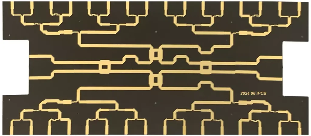
At high frequencies, the parasitic effect of the collector inductor element is prominent and the distribution parameters are unstable and are less often used. At this time, the microstrip line is widely used in the design of RF circuits with its unique characteristics of stable distribution parameters and simple structure. The length and width of the actual microstrip line can be calculated based on the characteristic impedance and electrical length of the microstrip line.
Impedance is the combined response of a circuit to alternating current and contains resistance, inductance, and capacitance, symbolized as Z and measured in ohms. A thorough understanding of the concept of impedance helps optimize circuit design to ensure performance and stability. Impedance matching is an important way to improve signal transmission efficiency and minimize reflections, especially critical in high-frequency applications. Good matching not only improves power transfer efficiency, but also reduces circuit noise and improves system reliability.
