In modern electronic equipment, high-frequency and high-speed performance is gradually becoming the industry standard. People have higher requirements for the speed, precision and reliability of various electronic products, which makes the issue of signal integrity in PCB (Printed Circuit Board) design particularly important. When we talk about high-frequency, high-speed SOCKETs, signal integrity is not only related to the stability of the system, but also affects the end-user experience.
What is signal integrity? In layman’s terms, the signal in the interconnection line transmission process, will be subject to interconnection line and other factors interacting with the signal waveform distortion of a phenomenon, it can be said that the signal in the transmission is damaged, become ‘incomplete’. Signal integrity does not have a unique specification definition, from a broad sense, refers to the signal in high-speed products by the interconnecting wires caused by all the problems.
Core Principles of signal Integrity
Any signal connection relies on a transmission line that consists of a signal channel and a return channel together. Signals are constantly encountering transient impedances as they move along the transmission line. To ensure optimal signal transmission, it is necessary to ensure that the transient impedance is always constant, for example by ensuring that the transmission line has a consistent cross-section.
Each signal has its own specific return path, not just a simple earth connection. By analysing the return channel in depth, we can address the issues more effectively.
In the case of capacitance, the impedance of a signal decreases significantly when its edges change rapidly. Capacitance here covers not only externally added capacitance, but also parasitic capacitance inherent in the transmission line itself.
In the case of an inductor, once there is an abrupt change in the magnitude of the current or the number of turns of the magnetic line, a voltage is generated at its ends, which may lead to a number of problems such as reflection noise, crosstalk, switching noise, ground bounce, track collapse, and electromagnetic interference. In particular, when there is an abrupt change in the current flowing through the inductance of the ground loop, a voltage is generated on the ground loop, a phenomenon known as ground bounce, which is a source of switching noise and electromagnetic interference.
The signal bandwidth is the highest frequency value of the effective sinusoidal component, and this value is referenced to a square wave of the same frequency. In interconnect modelling, bandwidth is defined as this highest sinusoidal frequency at which the model can still accurately predict the actual performance of the interconnect.
In most cases, the results calculated by the formula for signal integrity are defined values or approximate estimates.
Lossy transmission lines cause degradation on the rising edge of the signal. Signal loss increases progressively with frequency due to the skin effect and cutoff loss.
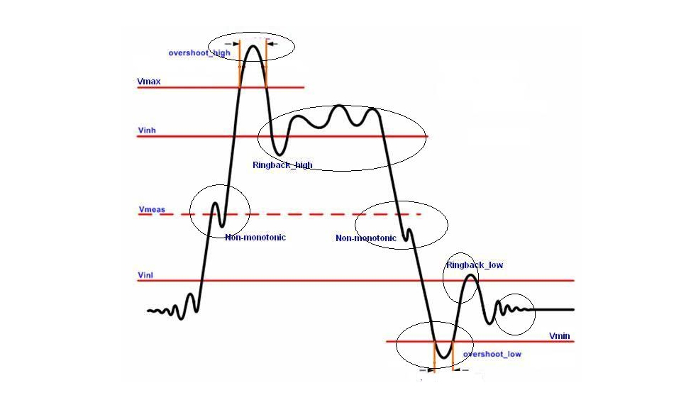
Why is PCB signal integrity needed?
Signal integrity plays an important role in high-speed digital systems. If there is a problem with signal integrity, the circuit may not function properly. The key electrical characteristic that affects signal integrity is the impedance of the interconnects, which is at the heart of the approach to signal integrity.
A signal is considered to have lost integrity in the following situations:
It deforms, i.e. its shape changes from the desired shape Unwanted electrical noise is superimposed on the signal, thus reducing its signal-to-noise ratio (S/N) It generates unwanted noise for other signals and circuits on the board
A PCB has the necessary signal integrity when:
All signals within it propagate without distortionAccording to or better than regulatory standards, its equipment and interconnections are not susceptible to extraneous electrical noise and electromagnetic interference (EMI) from other electrical products in the vicinityAccording to or better than regulatory standards, it does not generate, introduce, or radiate EMI in other circuits/cables/products connected to it or in the vicinity.
Impaired signal integrity is not the result of a single factor, but is caused by the intertwining of multiple factors in system design. Factors affecting signal integrity.
Interference and Noise: Signals in the transmission path may encounter interference and noise from the surrounding environment or other electronic devices, thus degrading the quality of the signal.
Media Transmission Characteristics: Various types of transmission media have unique electrical properties, such as resistance, capacitance, and inductance, which have a significant impact on the quality of the signal being transmitted.
Connection and Interface Devices: Connectors and interfaces are the hub of signal transmission and their performance is directly related to the quality of signal transmission.
High-speed Signal Transmission: As system frequency continues to rise, high-speed signals are more susceptible to perturbation by a variety of factors during transmission, making signal integrity issues more and more significant.
Circuit board design: The layout of the circuit board, the design of the wiring and the materials chosen will all have an impact on the quality of the signal transmission. The circuit board design may cause a series of problems such as signal reflection and crosstalk.
Signal Integrity Test Methods
In order to ensure the quality of signal transmission, it is necessary to test the signal integrity. The following are some commonly used test methods:
Time Domain Reflectometer (TDR): TDR is an instrument used to measure the reflection of signals on a transmission line. By sending a pulse signal to the transmission line and measuring the signal reflected back, you can determine whether there is any problem such as impedance mismatch or broken circuit on the transmission line.
Vector Network Analyser (VNA): The VNA is an instrument used to measure network parameters, and can measure the S-parameters (scattering parameters) of transmission lines, connectors, devices, etc. By measuring the S-parameters, you can understand the transmission characteristics of the network at different frequencies.
Logic Analyser: A logic analyser is an instrument used to capture and analyse digital signals. It captures digital signals on transmission lines and displays their waveforms, timing, and other information to determine the transmission quality of the signals.
PCB signal integrity is critical in modern electronic devices with high frequencies and speeds. By optimising design, selecting high-performance materials and rigorous testing, we can ensure stable signal transmission and improve overall system performance to meet the growing demands of users.
