As a multifunctional, high-precision measurement tool, multimeter plays an indispensable role in circuit board testing. Generally, the main purpose is to measure voltage, current and resistance. Multimeters are categorized into pointer multimeters and digital multimeters according to their display. It is a multifunctional, multi-range measuring instrument, also known as triple meter, multi-meter.
The basic principle and function of multimeter
A multimeter, known as a “universal measuring instrument”, is an instrument capable of measuring a variety of electrical quantities such as voltage, current and resistance. The basic principle is based on Ohm’s law, Kirchhoff’s law, and other basic principles of electricity, and the internal circuitry and sensors are used to realize accurate measurement of various electrical quantities.
Importance of Circuit Board Testing
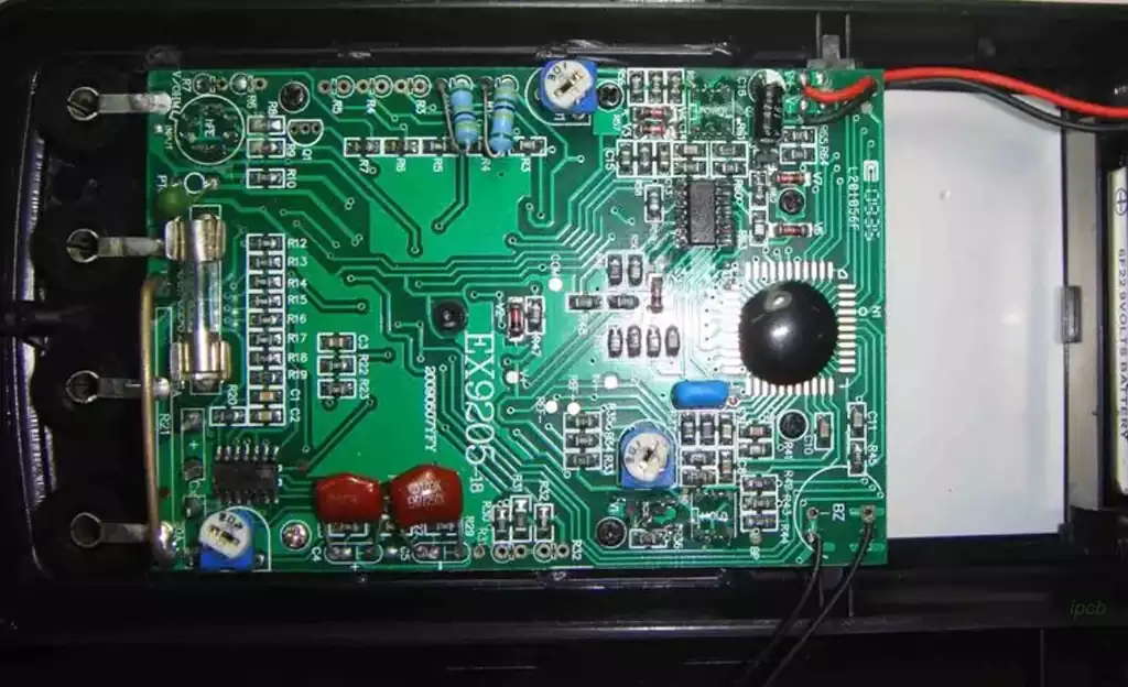
During the testing of circuit boards, the use of a multimeter can accurately detect the working status and performance of each component on the circuit board, so as to determine whether there is a fault or bad connection on the circuit board. Through timely detection and repair, equipment failures caused by circuit board problems can be avoided, and the stability and reliability of the equipment can be improved. Therefore, the use of multimeters to test circuit boards is essential to ensure the normal operation of equipment and maintenance of equipment safety.
How to test circuit board with multimeter
Current Measurement
In the circuit board current measurement, first of all, the multimeter should be adjusted to the current measurement file, and then the positive pole of the circuit board with the positive pole of the multimeter, the negative pole connection, to confirm the measurement range of the multimeter, to avoid overloading in the measurement process, which can cause damage to the circuit board. Then measure the current of the circuit board, if the current of the circuit board is normal, it can be assumed that the circuit board is normal, if the current value of the circuit board is too large or too small, it means that the circuit board may be faulty.
Voltage Measurement
In the circuit board voltage measurement, first adjust the multimeter voltage measurement file, the circuit board needs to be tested on the circuit point and the multimeter connected to the positive and negative poles correspondingly, and then the circuit point voltage measurement. If the voltage value of the circuit point is normal, the circuit board can be considered normal. Otherwise, the circuit board may have problems and need to be repaired or replaced.
Resistance Measurement
In the circuit board resistance measurement, you first need to adjust the multimeter to the resistance measurement file, the circuit board needs to measure the measurement of components. If the resistance of the components on the circuit board is normal, it can be assumed that the circuit board is normal. Otherwise, the circuit board may be faulty and need to be checked and repaired.
The process of testing a circuit board with a multimeter
Preparation stage: Make sure the circuit board to be tested has been disconnected from the power supply to avoid the danger of electric shock or short circuit during the testing process. At the same time, prepare the multimeter and select the appropriate measurement range and test head.
Appearance Inspection: Use the naked eye or a magnifying glass to carefully observe the components and connecting wires on the circuit board to check whether there is any obvious damage, breakage or bad contact.
Voltage test: Use the voltage measurement function of the multimeter, select the appropriate voltage level and measure the voltage value of each point on the circuit board. Compare with the design value or expected value to determine whether the voltage is normal.
Current Test: By connecting the multimeter in series in the circuit, select the appropriate current gear to measure the current value flowing through specific components or circuit segments. Judge the working status of the components according to the measurement results.
Resistance Test: Using the resistance measurement function of multimeter, select the appropriate resistance gear and measure the resistance value of components. By comparing the design value or standard value, judge whether there is damage or aging of the components.
Pass-through test: Use the ringing or resistance measurement function of the multimeter to detect whether the connection between the components on the circuit board is good. By measuring the resistance value between different points or listening to the ringing sound, we can judge whether the circuit is smooth or not.
Function test: According to the design and function requirements of the circuit board, gradually test whether each function module on the PCB board works normally. By operating the input devices such as switches and adjusting knobs, observe the response and performance of the output devices.
Record and analyze: During the testing process, record the data of each measurement point in detail and compare and analyze them. By comparing the designed value with the actual measured value, anomalies can be found and faults can be localized in time.
Multimeter as an important tool for circuit board testing, through mastering the basic principles and operating methods of the multimeter, combined with the characteristics and needs of the circuit board, we can carry out comprehensive and accurate testing of the circuit board to ensure the normal operation and reliability of the equipment.